Warnings
• Warning: follow these personal safety instructions very carefully. Save this manual for
future reference
• The RM series motors have been designed for the automation of roller shutters,
awnings and solar screens only. Any other use is improper and prohibited. MHOUSE
disclaims responsibility for any damage resulting from the improper use of the product,
the only use authorized by the manufacturer being the one described in this manual.
• Before installation, check that the tubular motor and accessories are suitable for use,
paying particular attention to the information in the “Technical Data” chapter. The nom-
inal couple and running time specified on the rating must be taken into consideration
when choosing the most suitable type of motor for a given application. Motors have
been designed for residential use only, at a 20% cycle with a continuous working time
of 4 minutes.
• The minimum diameter of the tube in which the motor can be installed is 52 mm.
• Installation must be carried out in full compliance with current safety regulations.
Remove all unnecessary electrical cables from the vicinity before installation. Deactivate
any mechanisms which are unnecessary for the motorised functioning of the product.
Minimum installation height is 2.5 m. Easy access must in any case be ensured. For
awning applications, the horizontal clearance between the fully open awning and any
stationary object must be at least 0.4 m. In the case of units for outdoor use, the pow-
er cable must be installed inside a protective duct. The command switch must be suit-
ably positioned away from moving components, at a height of at least 1.5 m and must
allow the operator to have an unobstructed view of the application.
• The tubular motor must not be subjected to crushing, impacts, falls or contact with any
kind of liquid. Do not perforate or drive screws into any part of the tubular motor. Do not
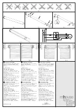
use multiple reverser switches for the same motor nor command multiple motors using
the same reverser switch (fig. 1). The motor must be kept away from any sources of
excessive heat, as well as flames. Any of the above may damage the motor and cause
it to malfunction or create dangerous situations. If this happens, stop using the product
and immediately contact the MHOUSE customer services department.
• Installation and maintenance must only be carried out if the device has previously been
disconnected from the power supply. If the disconnection device is not clearly visible,
fasten the following sign to it: "WARNING: MAINTENANCE WORK IN PROGRESS".
• Dispose of any packaging materials in compliance with the regulations locally in force.
• Keep people away from moving shutters. Do not operate the awning while work is in
progress nearby (e.g. window cleaning). In the case of automatic control, disconnect
the power supply. Do not allow children to play with the controls. Keep all remote con-
trols away from children.
• For maintenance and repairs contact a qualified technician. Check the balance springs
(if any) and power cords at regular intervals for signs of wear.
Description and Intended Use
In the 45Nm 8 couple versions (Fig.2), the tubular motors of the RM series (Ø45mm tube)
are electric motors, equipped with RPM reduction and terminating at one end with a shaft
on which the draw lock rings can be mounted. The motor is installed by inserting it into
the shutter, awning or solar screen tube, and moving them up or down. These motors are
equipped with an internal electric limit switch that, when properly adjusted, stops the
movement of the shutter/awning when it reaches the desired position.
Installation
Table 1 (Fig. 3)
A:
RM tubular motor
B:
Fastening clips or split pins
C:
Support and spacer
D:
Drag wheel
E:
Limit switch ring
F:
Limit switch ring nut
Prepare the motor as follows:
1.
Insert limit switch ring
(E)
into motor
(A)
until it enters the corresponding limit switch
ring nut
(F)
, to the point where the two splines fit together. Push them right into the
closing stop as shown in Fig. 4.
2.
Fit drag wheel
(D)
onto the motor shaft.
3.
Join the drag wheel to the pressure seeger.
4.
Insert the motor assembled in this way into the winding tube until the end of the ring
has also been inserted
(E)
.
5.
Fasten drag wheel
(D)
to the winding tube using screw (M4x10) in order to prevent the
axis of the motor from sliding or moving (Fig. 5).
6.
Finally, secure the motor head to the special support
(C)
with the spacer (if any), using
either the clips or split pin
(B)
.
Electrical connections
WARNING: For motor connections, an omnipolar disconnecting device with a 3-mm min-
imum distance between contacts must be provided for disconnection from the mains
power supply (disconnecting switch or plug and socket, etc.).
WARNING: carefully follow all the connection instructions. If you have any doubts do not
make experiments but contact MHOUSE Customer Service or consult the relevant tech-
nical specifications sheets which are also available on the web site "www.niceforyou.com".
An incorrect connection may be dangerous and cause damage to the system.
The cable used for the electrical connections of the RM tubular motors has 4 wires:
Electrical UP phase, electrical DOWN phase, Common wire (usually connected to the
Neutral) and Earth (unipotential protection connection). For the electrical connections see
table 2 and the diagram in Figure 6. The control and connection devices are not supplied
with the product.
Table 2
Brown
Electrical UP phase
Black
Electrical DOWN phase
Blue
Common
Yellow/Green
Earth
The motor’s electrical “up” and “down” phases are interchangeable, since the former
causes the motor to rotate in one direction, the latter in the opposite direction. The up and
down movements are determined by the side from which the motor is inserted in the
winding tube. To change the direction of rotation, switch the brown and black conduc-
tors.
Limit switch adjustment
The RM series tubular motors are equipped with a system of electromechanical limit
switches that interrupt the power supply when the awning or shutter reaches the open-
ing limit.
To adjust these limit positions according to your requirements, turn the two adjustment
screws that control the “UP”
▲
(stop in the raised position) and “DOWN”
▼
(stop in the
lowered position) movement of the awning/shutter. For proper identification of the adjust-
ment screws see figure 7 or 8 depending on whether the motor is to the left or right. For
externally-mounted shutters, see figure 9 or 10. The limit switch positions are preset by
the manufacturer at approximately 3 shaft rotations.
“DOWN” adjustment:
1.
Power the motor so it moves in the “DOWN” direction.
2.
Wait for the motor to stop, because the “DOWN” limit switch
▼
has been triggered.
3.
While the motor is still being powered, rotate the adjustment screw which corresponds
to the down
▼
anticlockwise (+), until you reach the required position.
“UP” adjustment:
1.
Power the motor so it moves in the “UP” direction.
2.
Wait for the motor to stop, because the “UP” limit switch
▲
has been triggered.
3.
While the motor is still being powered, rotate the adjustment screw which corresponds
to the up
▲
anticlockwise (+), until you reach the required position.
Maintenance
The tubular motor needs no particular maintenance.
What to do if… a brief troubleshooting guide.
Though an electrical phase is supplied with power, the motor does not turn: check to see
if the thermal overload protection has triggered (in this case just wait for the motor to cool
down); then make sure that the motor is powered at the correct mains voltage, measur-
ing between the Common wire and the supplied electrical phase; finally try powering the
opposite electrical phase. If the motor still does not turn there might be a serious mal-
function.
Disposal
This product is made from various kinds of material, some of which can be recycled, while
others must be disposed of. Make sure you recycle or dispose of the product in compli-
ance with laws and regulations locally in force.
WARNING:
Some electric components may contain polluting substances; do not dump
them.
Technical characteristics
The RM series tubular motors are produced by Nice S.p.a. (TV) I.
MHOUSE S.r.l. gs to the same group as Nice S.p.a..
Nice S.p.a., in order to improve its products, reserves the right to modify their technical
characteristics at any time without prior notice. In any case, the manufacturer guarantees
their functionality and fitness for the intended purposes.
Note: all the technical characteristics refer to a temperature of 20°C.
RM series tubular motors
Type:
Tubular motor for rolling shutters, awnings or solar screens, and similar applications.
Adopted technology:
Single phase, asynchronous motor, complete with epicycloidal, 3
stage reduction. Electromagnetic brake. Electromechanical limit switch.
Length of the electrical cable:
Approximately 3 m
Power supply:
230Vac (+10% -15%) 50Hz
Rated current:
Refer to the technical data specified on the label attached to each model.
Rated power:
Refer to the technical data specified on the label attached to each model.
Speed:
Refer to the technical data specified on the label attached to each model.
Torque:
Refer to the technical data specified on the label attached to each model.
Continuous operating time:
maximum 4 minutes
Work cycle:
Maximum 20%
Operating ambient temperature:
-20 ÷ 70°C
Not suitable for use in acid, saline or potentially explosive atmosphere:
No
Protection class:
IP44
Dimensions/weight:
Ø45mm tube; 567mm in length, 2700g in weight
MhouseKit “RM”
GB


