background image


Operating instructions MHM Digital V Pro V1_0.docx 

Page 18 of 52 


3.


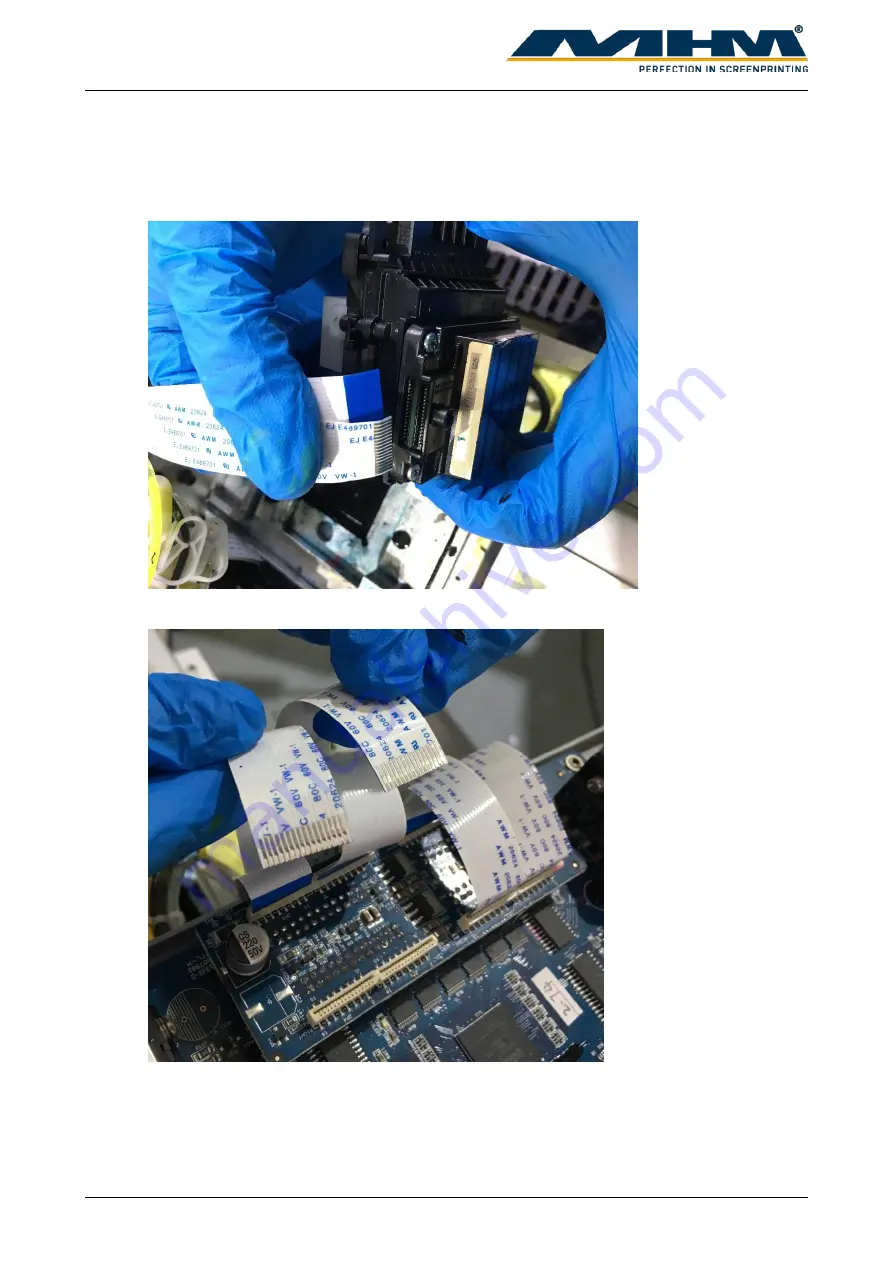
Ribbon cable connection 
Connect the ribbon cable as below on both left and right side of the print head. The ribbon 
cable will be facing opposite side. Each print head is connected with 4 ribbon cable. 


Connect the ribbon cable to the mother board accordingly. 


Summary of Contents for Digital V Pro

Page 1: ...Operating instructions MHM Digital V Pro V1_0 docx Page 1 of 52 OPERATING INSTRUCTIONS Original instructions 2020 Machines Highest Mechatronic GmbH Erl Austria ...

Page 2: ...e certain individual fittings and components may differ slightly from the model detailed in this document For any further questions regarding your MHM Digital V Pro please contact the MHM service team Wishing you every success with your future production Machines Highest Mechatronic GmbH Important Advice Regarding These Operating Instructions These Operating Instructions form an integral part of t...

Page 3: ...3 Ink station alignment 19 4 4 Ink Filling 21 5 Operating the printer controller 22 5 1 System requirements 22 5 2 User interface 22 5 2 1 General view 22 5 2 2 Toolbar 23 5 3 Installing the software 24 5 4 Using the software 25 5 4 1 Print head calibration 25 5 4 1 1 Vertical Print 26 5 4 1 2 Head Adjusts 29 5 4 1 3 Nozzle check 31 5 4 1 4 Both directions calibration 33 5 4 1 5 Horizontal distanc...

Page 4: ...leaning the caps 50 6 7 2 Cleaning the caps filter 50 6 8 Daily Maintenance 51 6 8 1 Cleanliness 51 6 8 2 Moisturizing 51 6 8 3 Lubrication 51 6 8 4 Print Head Maintenance 51 7 Optional Equipment and Replacement parts 52 8 Troubleshooting 52 9 Terms of the Guarantee 52 10 Support Customer Service and Hotline 52 ...

Page 5: ... actions 3 Material damage to the Digital V Pro 1 1 Description of Key Words and Symbols in the Operating Instructions In these operating instructions classified key words and symbols are used to identify dangers and items that require special attention Symbol Key word Meaning DANGER This symbol indicates possible risk for life CAUTION This symbol indicates danger of damage to property and or envi...

Page 6: ...its a bad odor stop using it and open a new cleaning agent o Close the fluid lid securely after used and store it out of reach of children Avoid storing it in locations subject to high temperatures high humidity and direct sunlight o Wash your hands thoroughly with soap and water after any fluid usage Store ink cartridges waste ink and cleaning agent out of the reach of children Wash your hands th...

Page 7: ...Valid Rules and Regulations The customer must comply with all regulations applicable in the country where the machine is located 2 Intended usage of the machine The MHM Digital V Pro is intended for the printing of substrates usually textiles such as T shirts but also paper or similar materials by means of digital printing in combination with an MHM carousel or oval screen printing machine 3 Data ...

Page 8: ... Pro V1_0 docx Page 8 of 52 3 1 Serial Number and Year of Manufacture Serial number and year of manufacture are indicated on the unit s type plate 3 2 Printer specification 3 3 Workspace The following workspace is required for the machine ...

Page 9: ...Operating instructions MHM Digital V Pro V1_0 docx Page 9 of 52 3 4 Ink consumption Two examples of expected ink consumption ...

Page 10: ...e printing press pallet Make sure the off contact of the pallet is at 0 2 Adjust the position of the print head Make sure the distance between the ink station and printing press pallet is at least 5cm 6cm away Upon delivery of the MHM Digital V Pro the consignment must be examined for external damage immediately In the case of any damages they must be documented and reported to Machines Highest Me...

Page 11: ...igital V Pro V1_0 docx Page 11 of 52 3 Move the ink station to its original position at the furthest left hand side as below 4 Move the ink station out and adjust the ink station 10 cm aside from the print pressing pallet as below ...

Page 12: ...0 docx Page 12 of 52 5 Make sure the printer main beam is parallel to the print pressing pallet as below 6 Adjust the printer y axis until it left 3 5 cm away from the print pressing pallet as bellow That is the point where the printer will stop ...

Page 13: ..._0 docx Page 13 of 52 7 Observe the steel metal and the back sensors Adjust them to make sure they were aligned This is the maximum point that the Y axis could be 8 Make sure the base of the print head is 4mm away from the print pressing pallet ...

Page 14: ...14 of 52 9 Level the printer until the reading of the 4 corners are only 0 5mm differences to the print head When the levelling is done lock the leg of the printer to make sure it does not move 10 There is an orange sensor as below which is not installed yet ...

Page 15: ...alled The sensor should face downward and when the print pressing pallet move upwards the sensor will light up Please make sure the distance between the sensor and print pressing pallet Is within 1mm 3mm when the pallet is raised Check if the sensor was functioning well on different pallet and off contact The sensor will light up if the print pressing pallet is move up The position of the sensor w...

Page 16: ...V1_0 docx Page 16 of 52 4 2 Print head installation 1 On the print head cartridge unscrew the screw from the point that the red arrows indicate 2 Damper connector From the top view of the print head remove the screw from the indicated position ...

Page 17: ...tions MHM Digital V Pro V1_0 docx Page 17 of 52 Install the connector on top of the damper as shown Make sure the rubber seal is properly installed and the screw is in correct position Attach the damper to the connector ...

Page 18: ...f 52 3 Ribbon cable connection Connect the ribbon cable as below on both left and right side of the print head The ribbon cable will be facing opposite side Each print head is connected with 4 ribbon cable Connect the ribbon cable to the mother board accordingly ...

Page 19: ... it relative position 4 3 Ink station alignment Ink station functions included to clean and protect the print head Ink station alignment is required under the following situation The anti drying caps are NOT fully covering the nozzles Cleaning wiper NOT able scrap of excess ink from the nozzles cleanly The height of the print head cartridge had been adjusted ...

Page 20: ...Operating instructions MHM Digital V Pro V1_0 docx Page 20 of 52 1 Select Setting from the main screen 2 Select Base option Enter the password 123 3 Select the Clean tab ...

Page 21: ...cyan C magenta M and yellow Y 2 Clean the ink bottle then add the ink respectively into its ink bottle 3 After the ink had been filled turn on the software and click the setting icon 4 The following window will pop out Under Fill Ink column select Heads click fill ink Observe the ink flow and stop when the print head is filled with ink ...

Page 22: ...iew Main menu No Name Description 1 Title bar Display the status of USB Dongle 2 Menu bar Drop down menu for the controller 3 Toolbar Display icons that indicate each menu items 4 Adjustment bar A menu to adjust the general setting for printing 5 Preview status area Display an image of files to be print and status of printing 6 Task list Display printing task queue and history 7 Printer status Dis...

Page 23: ... Print printing file 4 Stop Cancel printing 5 Pause Pause printing 6 Clean Display cleaning option 7 Reposition Return print head cartridge to starting position 8 Move Left Move print head cartridge outwards 9 Move Right Move print head cartridge inwards 10 Feeder forward Move print head cartridge to right 11 Feeder backward Move print head cartridge to left 12 Test Print Display test print option...

Page 24: ...2bit 64bit 4 Double click on setup exe and follow the wizard to complete the printer driver installation 5 Make sure you have properly connected the Printer controller dongle and USB from printer Turn on the printer after all installation 6 In PrintExp Folder run PrintExp exe in administrator mode 7 The following status shown that the USB driver is successfully installed and the printer controller...

Page 25: ..._0 docx Page 25 of 52 5 4 Using the software 5 4 1 Print head calibration The setting for Print head calibration could be found under Setting Calibration Before each print please raise the pallet up for the sensor to receive the printing signal ...

Page 26: ...ating instructions MHM Digital V Pro V1_0 docx Page 26 of 52 5 4 1 1 Vertical Print 1 Select Vertical Print The following alignment may include adjustment on print head cartridge and require proper handling ...

Page 27: ...al V Pro V1_0 docx Page 27 of 52 2 In the following figure the point where the red arrow pointed show the print head was not aligning Hence alignment should be done 3 Loosen the screw of the print head Loosen it only do not remove it ...

Page 28: ...the print head inward 5 For example the condition in step 2 figure the line was toward right So we should loosen the screw of the first red arrow and tighten the screw of the second arrow Tighten the screw that we loosen at step 3 Print and check the alignment again If the line was not straight redo the step 1 4 until you get a straight line Following is a figure of perfect vertical alignment ...

Page 29: ...libration select Head Status as below 2 Following is an example of printed line observe the red circled area It is the point where both print head joined We will adjust based on the difference of its distance The following alignment may include adjustment on print head cartridge and require proper handling ...

Page 30: ... docx Page 30 of 52 3 If the distance is large please loosen screw 2 3 4 and tighten screw 1 5 If the distance is small loosen screw 1 5 and tighten screw 2 3 4 4 Print the head status to check its alignment If is not aligned repeat step 2 3 again ...

Page 31: ...ion 2 Place a paper on the pallet to check the printing result 3 There s 2 way to select nozzle check function i Select Setting then select Calibration tab Before the nozzle check please make sure the height difference between the medium and print head is within 3 4mm Click Head Status for nozzle check ii Select Test Print from Toolbar then select Head Status ...

Page 32: ...e nozzle check pattern comes out with the following sign 5 Click the Clean icon Select as following 6 Conduct nozzle check again If the result is good then no need to clean the print head again Following diagram show a good condition of nozzle check Strong cleaning will consume more ink than normal cleaning ...

Page 33: ...Operating instructions MHM Digital V Pro V1_0 docx Page 33 of 52 5 4 1 4 Both directions calibration 1 Select Print Both direction calibration Key in the value for Y axis ...

Page 34: ...this is the best point Change the value of Y axis by minus 8 to the value of Y axis Then select Apply and OK Both Direction Calibration pattern 1 3 Print it again If at point 0 the line overlaps perfectly then calibration for both directions had been done If not please continue with step 1 2 Following is a figure of a good both direction calibration print ...

Page 35: ...Operating instructions MHM Digital V Pro V1_0 docx Page 35 of 52 5 4 1 5 Horizontal distance between heads calibration 1 Select Print to left ...

Page 36: ...the arrow pointing should be the baseline 3 show a straighter line The value for H2 to left should 3 in this case 3 Print it out again to check the alignment the line at 0 should be straight Following is a figure of what are we expecting If the line at 0 is not straight repeat step 1 2 4 Repeat step 1 2 and 3 for Print to right option ...

Page 37: ...head calibration 2 Following is the printed sample 0 is the baseline Observe the figure at which point both line stick together At 5 both line stick together so key in the value at H2 as 5 3 Print it out again to check the alignment the line at 0 should be straight Following is a figure of what are we expecting If the line at 0 is not straight repeat step 1 2 ...

Page 38: ...and prt To select a print file from your system 1 Browse external folder 1 1 Select the following icon on Toolbar 1 2 Select your print file and click Open 2 Select from Task list If user had already set the folder for print file the print file will automatically appear on Task List 2 1 Select Task List tab 2 2 Double click on the print file ...

Page 39: ...print file Note A thumbnail will be generated if the print file does not contain one 2 Ink statistics Display the estimated ink required for the print 3 Task Properties Display the properties for the file 4 Repeat Print Display the number of prints This could be change based on user requirement Select OK to confirm the print The file is now on Print List and ready to print 1 2 3 4 ...

Page 40: ...d 2 Right click on file under Print list and select Print Method 3 Shortcut Ctrl P to print the selected file The following properties of the print could be adjusted through the Adjustment bar before printing X margin position Direction of printing To right To left and Bi direction 5 4 2 3 Calibrating X axis 1 Select this icon 2 Following pop up window will appear Select Base Option ...

Page 41: ... below will appear as following Click Move at X Moto Calibration to calibrate the X axis for the print head 5 When the print head cartridge stops moving click Apply 6 Click Reposition for the print head to move back to its original position To ensure accuracy of the calibration repeat step 4 6 multiple times ...

Page 42: ... Click for the print head to back to its original position 2 Place a tape on above the front sensor This is the starting point of Y axis 3 Open up Basic parameters setting window Refer to calibration for X axis on how to open this window Key in the value that you preferred at Y moto calibration ...

Page 43: ...tructions MHM Digital V Pro V1_0 docx Page 43 of 52 4 Select Move at Y Moto Calibration 5 Use a ruler to measure the exact distance of the tape that you paste in step 1 and the metal plate shown in following figure ...

Page 44: ...ns MHM Digital V Pro V1_0 docx Page 44 of 52 6 Key in the exact value that you measured in step 5 in Y Run length Then click Calculate Do not click more than once 7 Click Apply then OK Calibration for Y axis had been done ...

Page 45: ...en c Get the registration of the printing screen based on the DTG printed sample 2 Estimating time a Print the desired image on a piece of fabric b The printer has a buffered time of 2 3 second between every printing Sum of the total time for a piece of printing and the buffer time 3 seconds will be the total required time for a print to finish c User could set the flash time from b to synchronize...

Page 46: ...ing damage on print head Should any spilling occurred immediately wipe off the excess ink with a cloth as it may leak into the machine and cause damage 6 2 Print Head Maintenance You need to maintain the print head if lines or other discrepancies appear in the printed image or if you notice the print quality has declined Print head maintenance keeps the print head in optimum condition to ensure th...

Page 47: ...he print head Use the cleaning swab to clean the print head Wipe the excess ink with the cleaning swab Notes Do not reuse the cleaning swab if it is dirty 6 Clean the ink station and cleaning squeegee if there is ink leakage stain 7 Click this icon for the print head back to its original position 8 Normal clean the print head as following 9 Conduct nozzle check to check its condition 6 4 Nozzle cl...

Page 48: ...print Ink station 6 6 Head Cleaning Wiper Head cleaning wiper is required to scrap off any excess ink on the print head in event of print head cleaning Excess ink that remains on top the wiper may dry off and accumulate over time Unclean wiper will fail to clean the print head nozzles perfectly and may cause damage on the print head and printing image If you notice obvious ink build up on the wipe...

Page 49: ...tting then select Base option 2 Enter the password 123 then select the Clean tab 3 Adjust the value in Move up to scraping pulses Increase will increase the raised height for the wiper during cleaning and vise versa You could check by performing a cleaning in the software Repeat the steps untill the print head could be clean perfectly ...

Page 50: ...e caps Ink may build up on the surrounding rubber of the caps cause the caps unable to seal tight with the printhead and suck out the ink properly overtime In such event use a piece of cloth to wipe off the excess ink Check with cleaning function if the ink could be vacuum properly by observing the ink droplets on the nozzles 6 7 2 Cleaning the caps filter If inks are spilled out during ink fillin...

Page 51: ...on the humidity and surrounding temperature If the temperature is too high ink dry out easily it will affect the printing quality and clog the print head easily 2 When the print head is not in use please make sure it is back at its original position Do not hang it in the air for a long period of time 3 If the external printer is not able to absorb ink efficiently please change it immediately Other...

Page 52: ...d solution to the error Waste ink did not flow out after head clean 1 Check if the motor is functioning 2 Check the print head and ink station make sure both are air tight 3 Check the tubing make sure it is not leaking or folded 4 Change the ink suction cap Double image formed when printing 1 Check the distance between the print head and medium is within 3mm 2 Check the alignment again and align i...

Reviews: