
Maintenance
3 —9
Installation and User Manual
5.
Turn the input circuit breaker off.
6.
Connect customers equipment.
7.
Energize system.
8.
Repeat Step #4 and adjust as needed.
9.
Be sure over/under detect is connected and if input breaker trips or there is no output voltage, re-calibrate the
detect board or replace board if defective.
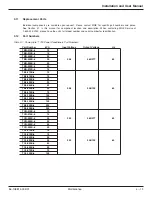
3.7
Unit Component Location Diagrams
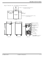
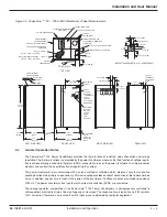
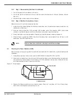
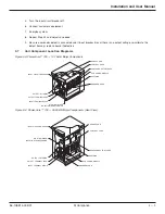
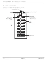
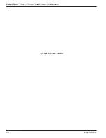
Figure 3-3: Power-Sure™ 700 — 10-15kVA Major Components.
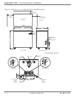
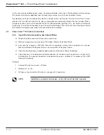
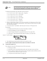
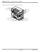
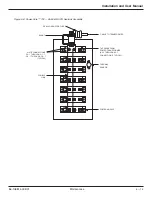
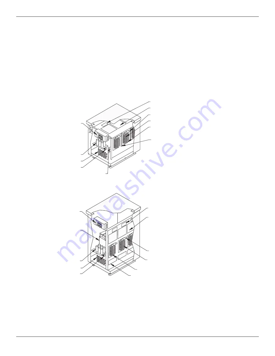
Figure 3-4: Power-Sure™ 700 — 25-30kVA Major Components (Rear View).
SENSE CARD
CONTROL CARD
INPUT CIRCUIT BREAKER
MULTI-SHIELDED
ISOLATION TRANSFORMER
OUTPUT FILTERING
OUTPUT TERMINAL PADS
INPUT TERMINAL BLOCK
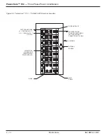
SNUBBER CARD
HEATSINK
SCR POWER MODULE
SEMI-CONDUCTOR FUSES
SENSE CARD
CONTROL CARD
SEMI-CONDUCTOR FUSES
SCR POWER MODULE
HEATSINK
SNUBBER CARD
INPUT CIRCUIT BREAKER
OUTPUT FILTERING
OUTPUT TERMINAL PADS
INPUT TERMINAL BLOCK
MULTI-SHIELDED
ISOLATION TRANSFORMER
86-108814-00 B01