


MFJ-933C
High-Efficiency Magnetic Loop Tuner
Instruction & Technical Manual
1.
TUNING:
This permits adjustment of the Butterfly capacitor.
2.
MATCHING:
This matches the tuned loop to a 50Ω coaxial cable.
3.
PVC MOUNT:
This is the mount point for the PCV cross assembly.
4.
COAX OUTPUT:
This is one of two
output
ports for using a coax loop instead of wire.
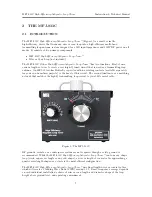
The MFJ-933C
High-Efficiency Magnetic Loop Tuner
™
front panel controls and indicators function
to permit matching the wire or coax loop to the coaxial line at the input of the tuner. Refer to
Figure 4 and the numbered component locations.
1.
LOOP CONNECTORS:
Connect wire loops here.
2.
COAX INPUT:
Connection to transceiver.
A wire loop antenna connects to the Loop Connectors with the two wing nuts provided on the
Loop Connector standoff rods. RF from the transceiver is input at the rear coax port. Care must
be taken not to disturb the wires leading from the lugs on the Loop Connector stand-off rods and
entering through the back of the tuner. The connection points must be kept clean at all times.
This unit is
not
intended for outdoor installation except during portable operation and must be
protected from the elements.
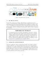
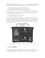
Figure 5: Rear-panel Connections: 1.) Wire loop connectors, 2.) Coax input
3
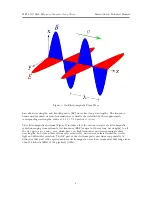
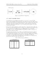
LOOP THEORY
A magnetic loop antenna is one that is characterized by low-noise reception, working well even
when mounted at ground level, and a circumference of less than
1
/
3
wavelength. The ideal small
transmitting antenna would have performance equal to a large antenna, and the MFJ-933C
-9-
Summary of Contents for MFJ-933C
Page 18: ...USER NOTES ...


