MFJ-5124K/Y Radio Interface
Instruction Manual
©
2005-2006 MFJ Enterprises, Inc.
11
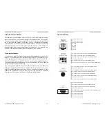
Firmware Version Number
The firmware version number of the MFJ-5124 can be read using the analog
meter on the MFJ-991/993/994 auto tuners via the interface cable. To obtain the
firmware version number, place jumper JP1 on the “A” position, jumper JP2 on
the “C” position, and then turn on the radio’s power. After the initial bouncing
of both needles on the auto tuner, the reflected needle will bounce repetitively
with approximately five seconds pause between intervals. The number of
bounces within each interval indicates the version number. For example, two
bounces of the reflected needle represent firmware version number 2.
Technical Assistance
If you have any problem with this unit first check the appropriate section of this
manual. If the manual does not reference your problem or your problem is not
solved by reading the manual, you may call
MFJ Technical Service
at 662-323-
0549 or the
MFJ Factory
at 662-323-5869. You will be best helped if you have
your unit, manual and all information on your station handy so you can answer
any questions the technicians may ask.
You can also send questions by mail to MFJ Enterprises, Inc., 300 Industrial
Park Road, Starkville, MS 39759; by facsimile (FAX) to 662-323-6551; or by
email to [email protected]. Send a complete description of your
problem, an explanation of exactly how you are using your unit, a complete
description of your station, and the unit’s firmware version number.
MFJ-5124K/Y Radio Interface
Instruction Manual
12
©
2005-2006 MFJ Enterprises, Inc.
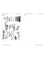
Connector Pinout
+13.8 V DC input ( A)
+13.8 V DC input ( A)
+13.8 V DC input ( A)
Ground
Ground
TT/TX
TX INH
TS/RX
1
1
1
7
8
6
5
4
3
2
1
12345678
MFJ-5124
TO RADIO
Front Panel View
Pin 1 (Ground) connects to pin of
lug.
Pin 2 (TT) connects to pin 6 of
TO RADIO plu
Pin (Ground) connects to pin 5 of
TO RADIO plug.
Pin 5 (TS) connects to pin 8 of
TO RADIO plug.
TO RADIO p
4
the TO RADIO p
the g.
3
the
Pin 4 is not connected.
the
Pin 6 (+13.8V) connects to pins 2 and 3 of the
lug.
1
3
2
4
6
5
Kenwood
AT or ACC
Rear Panel View
1
2
3
4
5
6
(TX INH) connects to pin 7 of
lug.
(SENSE) connects to pin 5 of
lug.
g.
RX
Pin 8 (+13.8V) connects to pin 3 of
lug.
Pin 1
the TO RADIO p
Pin 2 is not connected.
Pin 3
the TO RADIO p
Pin 4 (TX) connects to pin 6 of the TO RADIO plu
Pin 5 (
) connects to pin 8 of the TO RADIO plug.
Pin 6 (Ground) connects to pin 4 of the TO RADIO plug.
Pin 7 is not connected.
the TO RADIO p
1
2
3
4
5
6
7
8
Yaesu
CAT/TUNER
Rear Panel View
1
2
3
4
5
6
7
8
Pin 1 is not connected.
Pin (TX) connects to pin 6 of the TO RADIO plu
Pin (
) connects to pin 8 of the TO RADIO plug.
Pin 4 is not connected.
Pin (Ground) connects to pins 4 and of the TO RADIO plug
Pin 6 is not connected.
Pin 7 is not connected.
Pin 8 is not connected.
Pin 9 is not connected.
2
g.
3 RX
5
5
.
Yaesu
CAT
Rear Panel View
1
1
2
3
4
5
6
7
8
9
1
1
2
3
4
5
6
7
8
9

