background image

MFJ-998 Legal Limit IntelliTuner Automatic Antenna Tuner 

Instruction Manual 

©

 2007-2010 MFJ Enterprises, Inc. 


19

WARNING: Amplifier Bypass Control

TM

 is a safety precaution; the tuner and amplifier are in 

danger of being damaged if this function is turned off. 


Meter Range Menu 

Allows you to select the meter scale range.  In the 300 watts (low) range, the forward full scale is 300 
watts and the reflected full scale is 60 watts.  In the 3000 watts (high) range, the forward full scale is 3000 
watts and the reflected full scale is 600 watts (multiple the meter reading by 10).  Auto range 
automatically sets the meter scales according to the input RF power to the tuner.  Forward power greater 
than 300 watts or reflected power greater than 60 watts automatically sets the meter to the high power 
range.  Forward power less than 250 watts and reflected power less than 40 watts automatically set the 
meter to the low power range.  Refer to Figures 16 and 17 for the on-screen Meter Range indicators.  
Default is AUTO Range. 
 

Peak Hold Menu 

When the peak hold function is ON, the highest activated segment of the forward bar meter remains 
visible for about one second, so that you can more easily read it.  When OFF, the meter functions 
normally.  Default is ON. 
 

Memory Menu 

Turns the antenna memory on and off.  The “memory resolution” is the width of frequency spectrum that 
the tuner recognizes as being the same as a tuned frequency already in memory.  The memory resolution 
is approximately 0.1 percent of the lower frequency of each amateur band.  For example, the memory 
resolution on the 40-meter band (7000 to 7300 kHz) is 7 kHz; if the tuner has memorized a setting for 
7050 kHz, it will automatically call up this setting for any frequency from 7047 to 7053 kHz.  Memory 
resolution is smaller at lower frequency to accommodate the higher antenna Q and larger at higher 
frequency where the antenna Q is lower.  The memory resolutions for the HF amateur bands 160 through 
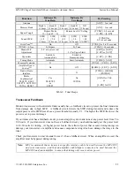
10 meters are: 
 

Meter 

Frequency Range (kHz) 

Memory Resolution (kHz)

160 

1800 – 2000 

75/80 

3500 – 4000 

60 

5330.5, 5346.5, 5366.5, 5371.5 and 5403.5 

5 memory locations 

40 

7000 – 7300 

30 

10100 – 10150 

10 

20 

14000 – 14350 

14 

17 

18068 – 18168 

18 

15 

21000 – 21450 

21 

12 

24890 – 24990 

25 

10 

28000 – 29700 

28 


Table 1.  Memory Resolution. 

 
The memory resolution for non-amateur frequency bands between 160 and 10 meters is approximately 
0.2 percent of the lower frequency of each band.  There are over 2500 memory locations for each memory 
bank, and each antenna has four memory banks (A-D).  Tuner settings are stored in memory separately 
for Antenna 1 and Antenna 2 (settings for single-wire antenna are stored as Antenna 1).  This provides 
memory for up to eight different antennas.  Refer to Figures 16 and 17 for the on-screen Memory 
indicator.  Defaults are memory banks 1A and 2A ON. 

Summary of Contents for Legas Limit IntelliTuner MFJ-998

Page 1: ... Before Operating Equipment MFJ ENTERPRISES INC 300 Industrial Park Road Starkville MS 39759 USA Tel 662 323 5869 Fax 662 323 6551 COPYRIGHT 2007 2010 MFJ ENTERPRISES INC C Model MFJ 998 VERSION 1E Legal Limit IntelliTuner Automatic Antenna Tuner TM ...

Page 2: ...itional handbooks or other official publications The copy of this manual provided to the customer will not be updated to reflect current data Customers using this manual should report errors or omissions recommendations for improvements or other comments to MFJ Enterprises 300 Industrial Park Road Starkville MS 39759 Phone 662 323 5869 FAX 662 323 6551 Business hours M F 8 4 30 CST ...

Page 3: ...Adjustment 6 LCD Display 6 LCD Contrast Control 6 ANT Button 6 MODE Button 6 C UP and C DN Buttons 6 L UP and L DN Buttons 6 TUNE Button 7 StickyTuneTM 7 Automatic Semi Automatic Tuning Mode 7 POWER Button 7 Back Panel 9 Amp Enable In 9 Amp Enable Out 9 Power 9 Radio Interface 9 Jumper JP1 10 Serial Port 12 Transmitter 12 Ground 12 Wire 12 Antenna 1 12 Antenna 2 12 Installation 13 SWR Wattmeter 13...

Page 4: ...enu 20 SWR Beep Menu 20 Beep Menu 20 Refresh Menu 20 Radio Interface Menu 20 Push Tune 0 5s Menu 21 LC Limit Menu 21 OPERATION Manual Tuning 21 Morse Code and Beeps 22 Transceiver Foldback 23 Grounding Hints 24 Antenna System Hints 24 Coaxial Cable Selection 24 Location 24 Matching Problems 25 APPENDICES Resetting the Tuner 26 Factory Defaults 26 Disable Radio Interface 27 Delete Entire Antenna Me...

Page 5: ...ections for FTDX 9000 series of radios 40 Operation for FTDX 9000 series of radios 41 Yaesu Radio Interface MFJ 5114Y4 41 Connections for FT 2000 series of radios 41 Operation for FT 2000 series of radios 41 In Case of Difficulty 42 Technical Assistance 42 List of Accessories 42 Circuit Block Diagram 43 FIGURES Figure 1 Typical Installation Block Diagram 5 Figure 2 MFJ 998 Front Panel 5 Figure 3 M...

Page 6: ... Tuner Instruction Manual 2007 2010 MFJ Enterprises Inc iv Figure 17 Tuner Indicators 17 Figure 18 Power On Operations 26 Figure 19 MFJ 998 Circuit Block Diagram 43 TABLES Table 1 Memory Resolution 19 Table 2 Tuner Beeps 23 Table 3 Failure Messages 28 ...

Page 7: ...anges are 0 to 24 μH and 0 to 3900 pF input or 0 to 970 pF output And once a match is found the matching network values can be displayed so you may design your own fixed matching network if desired The MFJ 998 IntelliTunerTM learns and remembers When you transmit it automatically adjusts for minimum SWR and remembers the frequency and tuner settings safely stored in non volatile memory The next ti...

Page 8: ...cuit Direct read out of matching L C values available after tuning 1 8 to 30 MHz continuous frequency coverage Adjustable target SWR from 1 0 to 2 0 Adjustable SWR threshold from 0 5 to 1 5 Adjustable amp bypass SWR from 1 5 to 3 0 Lighted cross needle SWR wattmeter with high low and auto range options Multifunction backlit LCD display with contrast control Numeric readings for SWR forward and ref...

Page 9: ...iver Protection Like all MFJ IntelliTunersTM the MFJ 998 can provide automatic control interfacing with most popular transceivers through optional transceiver interface cables When interfaced to your transceiver with the appropriate cable the MFJ 998 automatically puts your transceiver into a low power CW tune mode when tuning is initiated More details are provided in the Radio Interface section o...

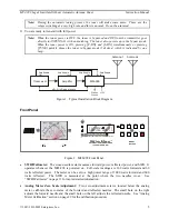
Page 10: ... OUT on the MFJ 998 to the AMPLIFIER ENABLE INPUT on your amplifier Note If you use an amplifier keying interface between your transceiver and your amplifier such as the Ameritron ARB 704 this amplifier keying interface may be placed either between the transceiver and MFJ 998 or between the MFJ 998 and amplifier 6 If available connect an MFJ 5114 transceiver control cable between the MFJ 998 and y...

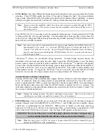
Page 11: ...tallation Block Diagram Front Panel AUTOMATIC ANTENNA TUNER 1500 Watts SSB CW MFJ IntelliTunerTM C UP L UP ANT TUNE MODE POWER C DN L DN MODEL MFJ 998 SWR 14 100MHz 1 2 FWD 1000 REF 10 HI x10 1 1 2 1 5 2 3 SWR 0 25 50 75 100 PWR 300 Figure 2 MFJ 998 Front Panel SWR Wattmeter The cross needle meter measures forward power reflected power and SWR It operates whenever the MFJ 998 is powered on Full sc...

Page 12: ...indicate bank B three beeps indicate bank C four beeps indicate bank D and five beeps indicate antenna memory is OFF The Memory indicator on the main display also indicates the selected bank Pressing the ANT button switches the antenna or bank only when there is no RF power Also the tuner setting for the selected antenna or bank if available is instantly restored from memory when enabled MODE Butt...

Page 13: ...TM is enabled a bar appears on top of the Auto Semi indicator and the tuning process starts automatically when the transmitter is keyed with at least five watts of power regardless of the SWR This works in both automatic and semi automatic modes To toggle the StickyTuneTM mode on and off press and hold the TUNE button for two seconds One beep indicates on and two beeps indicate off Default is off ...

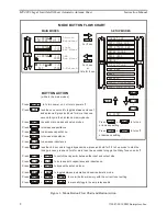
Page 14: ...crease capacitance Press to increase capacitance Press to switch main modes and setup modes Press less than one second to toggle between antenna 1 and antenna 2 press and hold for more than one second to cycle the 4 antenna memory banks Press in to turn power on out to turn power off Press or to turn on or increase setting C UP L UP C DN L DN Press or to turn off or decrease setting while in the m...

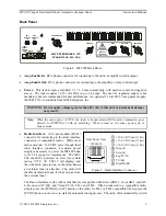
Page 15: ...and RF from the transmitter goes directly to ANTENNA 1 with no matching When turned on the tuner powers up in bypass mode Radio Interface An 8 pin modular RJ 45 connector for connecting to the tuner interface connector of compatible radios While most radios provide 13 8 VDC power though their tuner interface connector a separate power supply is necessary to power the MFJ 998 due to its 1 4 amp pow...

Page 16: ...The MFJ 5114A interface cable provides control signals between an Alinco radio and the MFJ automatic tuner Supported Alinco radios are DX 70 DX 77 DX 701 DX 801 and any Alinco radio that supports the Alinco EDX 2 tuner Press the radio s TUNE button to start the tuning process for DX 70 press FUNC then TUNE Refer to Alinco Radio Interface on page 32 for connections and operation Pin 1 Ground connec...

Page 17: ...face provides control signals between a Yaesu radio and the MFJ automatic tuner Supported Yaesu radios are FT 100 FT 450 FT 857 FT 897 FT 950 and any Yaesu radio that supports the Yaesu FC 30 tuner Push and hold the radio s TUN or TUNE key to start the tuning process Make sure jumper JP1 is installed Refer to Yaesu Radio Interface MFJ 5114Y on pages 35 to 38 for connections and operation TX INH co...

Page 18: ...henever the MFJ 998 s TUNE button is pushed MFJ recommends that the Yaesu tune power setting be set to 20 watts Yaesu menu 145 tGEn TUN PWR during the tune process Refer to Yaesu Radio Interface MFJ 5114Y4 on page 41 for connections and operation Center pin KEY connects to pin 6 of Radio Interface Plu Ground GND connects to pins 4 and of Radio Interface Plug 5 g 1 2 KEY GND Figure 11 Yaesu Interfa...

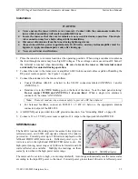
Page 19: ...er as follows Coaxial feedlines RG 8 U or better to the SO 239 connectors labeled ANTENNA 1 and or ANTENNA 2 Random wire to the WIRE binding post on the back of the tuner Note the back panel warning Do not connect WIRE and ANTENNA 1 at same time When a single wire antenna is connected it becomes ANTENNA 1 Note Route all random wire antennas safely to prevent a RF burn hazard For balanced feedlines...

Page 20: ...ow Various tuner indicators are shown on all four main menus Antenna 1 2 IntelliTuneTM Radio Interface Memory LC Limit Auto Range Auto Semi and StickyTuneTM Refer to Figures 16 and 17 for details on the displayed information Note In sideband mode the frequency readout on the tuner display jumps around to different frequencies while transmitting and stops on another frequency when un keyed This is ...

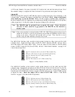
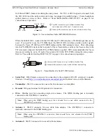
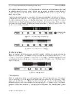
Page 21: ... on screen Auto Range indicator 0 25 50 75 100 PWR 300 Multiple scale by 10 Figure 13 Power Bar Meter High Range 0 25 50 75 100 PWR 300 Figure 14 Power Bar Meter Low Range SWR Bar Meter Menu Shows the frequency SWR forward power and SWR bar meter A SWR scale is printed just below the display on the front panel The 12 block 31 segment SWR bar meter indicates SWR of 1 0 1 1 1 2 1 3 1 4 1 5 1 6 1 7 1...

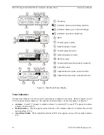
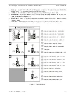
Page 22: ...e 1 2 3 4 5 6 7 8 9 10 11 12 13 14 6 7 1 2 3 4 5 8 9 1 2 3 4 5 6 10 1 2 3 4 5 6 11 12 13 14 6 2 3 4 5 Figure 16 Main Mode Menus Display Tuner Indicators Various tuner indicators are shown on the main menus to indicate tuner status Refer to Figures 16 and 17 for locations of these indicators The number enclosed within is the item number of Figure 17 Antenna A small 1 appears to indicate antenna 1 i...

Page 23: ...kyTuneTM is ON a bar appears on top of the Auto Semi indicator 30 2 2 4 3 3 3 3 Enlarged Views of Indicators 22 15 17 20 21 18 19 16 22 17 20 21 18 19 23 27 28 24 27 28 25 27 28 26 27 28 30 29 Appears when Antenna 1 is selected Appears when Antenna 2 is selected Appears when Alinco Icom is selected Appears when Kenwood is selected Appears when Yaesu is selected Appears when Yaesu MP is selected re...

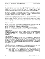
Page 24: ...back to the main mode Press the ANT button to cycle backward through the setup menus Press the C UP or L UP button to increase or turn on the setting for the current setup menu Press the C DN or L DN button to decrease or turn off the setting for the current setup menu Target SWR Menu Allows you to set the target SWR from 1 0 to 2 0 The tuning process will stop when a match with an SWR less than o...

Page 25: ... resolution is the width of frequency spectrum that the tuner recognizes as being the same as a tuned frequency already in memory The memory resolution is approximately 0 1 percent of the lower frequency of each amateur band For example the memory resolution on the 40 meter band 7000 to 7300 kHz is 7 kHz if the tuner has memorized a setting for 7050 kHz it will automatically call up this setting f...

Page 26: ...ish this function can be turned off Default is ON SWR Beep Menu Turns the audio SWR meter on and off The audio meter is a series of beeps where one beep indicates SWR of 1 5 or less two beeps indicate SWR of 1 6 to 2 0 three beeps indicate SWR of 2 1 to 2 5 and four beeps indicate SWR of 2 6 to 3 0 For SWR above 3 0 SWR di di dit di dah dah di dah dit will be sent on CW This functions independent ...

Page 27: ... prevent matching of extreme load impedance outside the tuner s specification which may result in excess voltage and or current across the tuner s components This setting is not stored in non volatile memory and reverts back to the default when the tuner power is cycled Refer to Figures 16 and 17 for the on screen LC Limit indicator Default is ON Note If this feature is turned OFF it will be re se...

Page 28: ...uning routine is automatically started when at least five watts of power is applied and the SWR is a preset amount above the preset target SWR In semi automatic mode the tuning routine starts only when the TUNE button is pressed The Auto Semi indicator on the main display indicates the selected mode Pressing TUNE C DN and L DN simultaneously overwrites the tuner memory with the current tuner setti...

Page 29: ... for YES or L DN for NO Table 2 Tuner Beeps Transceiver Foldback Modern transceivers with solid state finals usually have a foldback circuit to protect the final transistors from damage due to high SWR A foldback circuit detects the SWR during transmit and reduces the output power as the SWR rises above a preset threshold usually 2 1 The higher the SWR the lower the power is set to prevent damage ...

Page 30: ... fences may work especially if they are connected together with multiple wires but the best RF grounds are radial systems or multi wire counterpoises Radials and counterpoises provide large low resistance surfaces for RF energy RF and lightning travel on the surface of conductors Braided or woven conductors have high surface resistance to lightning and RF Ground leads for RF and lightning should h...

Page 31: ...he tuner on 40 meters This places enormous strain on the tuner since voltages can reach several thousand volts This can cause component arcing and heating The following suggestions will reduce difficulty in matching an antenna with a tuner Never center feed a half wave multi band antenna with a high impedance feedline that is close to an odd multiple of a quarter wave long Never center feed a full...

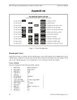
Page 32: ...R POWER POWER POWER POWER POWER POWER POWER POWER POWER L UP C UP MODE TUNE ANT C UP C DN L DN L UP TUNE TUNE C UP C DN POWER Press and hold to calibrate the SWR bridge Figure 18 Power On Operations Resetting the Tuner Each time the tuner is powered off the microprocessor saves all memories and configurations to non volatile memory ready to be used the next time the unit is turned on and transmit ...

Page 33: ...ttons while turning the power back on A confirmation message DELETE ANTENNA will display Press the YES C DN button to delete the antenna memory a progress bar and DELETED will display or press the NO L DN button to cancel CANCEL will display Release the button to resume normal operation Remember that the selected antenna memory will be lost Delete Antenna Memory Bank To delete an antenna memory ba...

Page 34: ...E 6 The unit then tests its non volatile memory Notice this step will reset the unit to its factory default settings 7 If the unit is okay a repetitive message PASS will be displayed and sent as Morse code di dah dah dit di dah di di dit di di dit If there is a problem a failure message will be displayed and sent repetitively 8 Once you have confirmed that the audio is okay turn the unit off 9 Tur...

Page 35: ...e damage to the tuner can result To test the relays and their control circuitry press and hold the C DN button while turning the power on The message RELAY TEST will appear Six numbers representing the relays will be shown on the display The ANT C UP L UP MODE C DN and L DN buttons corresponding to the position of the relay numbers on the display are used to toggle each relay on and off Press butt...

Page 36: ...st trimmer capacitor VC1 located on the small circuit board mounted in front of the TRANSMITTER connector for minimum reflected power Notice the reflected meter movement is exaggerated for easier calibration 7 Key the transmitter to 100 watts output and adjust the FWD trimpot VR1 located next to the big integrated circuit until the display shows forward power of FWD 100 watts The forward meter als...

Page 37: ...rom the tuner 12 screws with a Phillips screwdriver 3 Connect the 50 ohm dummy load to the ANTENNA 1 connector connect the transmitter to the TRANSMITTER connector on the tuner 4 Turn on the power to the transmitter Set and lock the frequency to exactly 29 000 MHz 5 Press and hold both the C DN and L DN buttons while turning the tuner power on Both meter needles will go to full scale and a message...

Page 38: ...not fuse the DC power to the tuner and damage to the radio can occur if the interface s power connection comes in contact with ground 4 Connect the 5 pin molex connector to the mating 5 pin molex connector marked as ACC on the back of the Alinco radio 5 Connect a 12V 1 5 amp DC source to the MFJ 998 6 Push the POWER button on the tuner to the in position and then power on the radio Operation The o...

Page 39: ...1 5 amp DC source to the MFJ 998 7 Push the POWER button on the tuner to the in position and then power on the radio 8 Some Icom radios such as the IC 706 automatically check to see if an external antenna tuner is connected during power on For other Icom radios such as the IC 718 the Tuner Type menu in the radio menu system must be enabled Refer to your radio s operating manual for accessing the m...

Page 40: ...enwood radio 6 Connect a 12V 1 5 amp DC source to the MFJ 998 7 Push the POWER button on the tuner to the in position and then power on the radio 8 Some Kenwood radios automatically check to see if an external antenna tuner is connected during power on For other Kenwood radios such as the TS 450S and the TS 690S the External Antenna Tuner menu in the radio menu system must be enabled Refer to your...

Page 41: ...itialize the radio regarding the tuner status 4 Turn the radio off Insert the 8 pin modular plug into the tuner s RADIO INTERFACE jack 5 Important Make sure the DC power to the radio has been turned off The radio does not fuse the DC power to the tuner and damage to the radio can occur if the interface s power connection comes in contact with ground 6 Connect the 8 pin mini DIN connector to the ma...

Page 42: ...cur if the interface s power connection comes in contact with ground 6 Connect the 8 pin mini DIN connector to the mating 8 pin mini DIN connector marked as TUNER on the back of the radio 7 Connect a 12V 1 5 amp DC source to the MFJ 998 8 Push the POWER button on the tuner to the in position and then power on the radio Operation for FT 450 The operation of the MFJ 5114Y radio interface is similar ...

Page 43: ...ange the setting to TUNER h Press and hold the FUNC or F key for one second to save the new settings and exit to normal operation 4 Turn the radio off Insert the 8 pin modular plug into the tuner s RADIO INTERFACE jack 5 Important Make sure the DC power to the radio has been turned off The radio does not fuse the DC power to the tuner and damage to the radio can occur if the interface s power conn...

Page 44: ...nterface s power connection comes in contact with ground 6 Connect the 8 pin mini DIN connector to the mating 8 pin mini DIN connector marked as TUNER on the back of the radio 7 Connect a 12V 1 5 amp DC source to the MFJ 998 8 Push the POWER button on the tuner to the in position and then power on the radio Operation for FT 950 The operation of the MFJ 5114Y radio interface is similar to the opera...

Page 45: ...e setting can be set at 10 for all transceivers d Press ENT to exit the Menu mode 3 Insert the 8 pin modular plug into the MFJ 998 RADIO INTERFACE jack 4 Connect the 3 5 mm mono plug on the MFJ 5114Y3 to the REMOTE jack on the rear panel of the transceiver 5 Connect a 12V 1 5 amp DC source to the MFJ 998 6 Push the POWER button on the MFJ 998 to the in position The radio may be powered on either b...

Page 46: ...rt the tuning process When tuning is completed the radio will stop transmitting and you will be ready for operation on this frequency Connections for FTDX 9000 series of radios 1 Select YAESU MP 2K 9K in the tuner s Radio Interface setup menu Turn the tuner off 2 Before connecting the MFJ 5114Y3 to your radio set the maximum TUNE power of the radio as follows a On your transceiver enter the Menu m...

Page 47: ... the MENU key momentarily b Rotate the Main Tuning Dial knob until you see menu item 145 tGEn TUN PWR on the transceiver s display c Rotate the SUB VFO B knob to select 20 watts for best SWR accuracy For the FT 2000D we recommend that this be set to 50 watts if the user normally operates at 100 watts output power when power is turned down to 100 watts the TUNE power will reduce to 25 watts If the ...

Page 48: ...manual If the manual does not reference your problem or your problem is not solved by reading the manual you may call MFJ Technical Service at 662 323 0549 or the MFJ Factory at 662 323 5869 You will be best helped if you have your unit manual and all information on your station handy so you can answer any questions the technicians may ask You can also send questions by mail to MFJ Enterprises Inc...

Page 49: ...8 Circuit Block Diagram Transmitter Antenna 2 Antenna 1 Wire Impedance Sensor SWR Sensor Frequency Counter Memory Microcontrollers Relay Drivers Ground SWR Wattmeter Push Buttons LCD Display Buzzer User Interface Contrast Inductors 0 24 uH Capacitors 0 3900 pF L Network Serial Port Radio Interface Amp Enable In Amp Enable Out ...

Page 50: ...MFJ 998 Legal Limit IntelliTuner Automatic Antenna Tuner Instruction Manual 2007 2010 MFJ Enterprises Inc 44 Notes ...

Page 51: ...ervice Department at 662 323 0549 or the MFJ Factory at 662 323 5869 4 This warranty does not apply to kits sold by or manufactured by MFJ Enterprises Inc 5 Wired and tested PC board products are covered by this warranty provided only the wired and tested PC board product is returned Wired and tested PC boards installed in the owner s cabinet or connected to switches jacks or cables etc sent to MF...

Page 52: ...MFJ 998 Manual Version 1E Printed In U S A 02 2010 300 Industrial Park Road Starkville MS 39759 MFJ ENTERPRISES INC ...

Reviews: