Meyra TA R-Net Omni 2 Operating Manual Download Page 29

30

29

INDIVIDUAL FEATURES/

SETTINGS


Not all features described here may be 
available for your wheelchair.

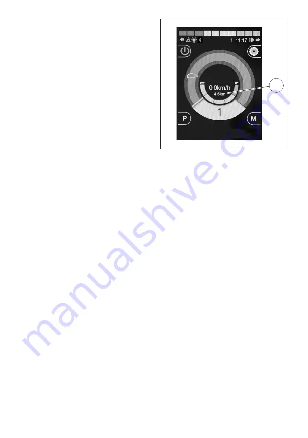
Odometer (total kilometres)

The LCD display shows the 

total number of 

kilometres

 (30), up to a maximum of 

99,999

.


Only the kilometres travelled in a for-
ward direction are shown.

Trip counter

The LCD screen can display the 

daily kilo-

metres travelled

 (30), up to a maximum of 

9,999.9

.


Only the kilometres travelled in a for-
ward direction are shown.

You can toggle between the different 
odometer display options in the 

Distance


settings menu.


Follow the instructions in the chapter 

Settings menu

 on page 31.


The trip counter can be reset as need-
ed.

Resetting the trip counter

The trip counter can be reset in the 

Distance


settings menu.


The trip counter will then display 

0.0 km


on the LCD screen.

Summary of Contents for TA R-Net Omni 2

Page 1: ...OPERATING MANUAL R Net Omni 2 This product fulfils the requirements of Regulation EU 2017 745 on medical devices 300 37 UM Omni 2 GB 06 2021 vers 1 0...

Page 2: ...joystick modules 7 Overview 8 Omni 2 Control Module 8 Push button control panel 8 Distribution box connections 8 LCD screen 9 Sensors 10 Attendant control 11 Control panel buttons 11 LED indicators 1...

Page 3: ...5 Selecting a control mode 25 Electronic adjustments 26 Selecting electronic seat adjustments 26 Functional electronic seat adjustments 26 Complex electronic adjustments 27 Individual features setting...

Page 4: ...nance repair 40 Repairs 40 Service 40 Technical safety inspections 40 Daily inspections 40 Weekly inspections 40 Annual inspections 40 Technical data 41 Warranty guarantee 41 Warranty certificate 42 N...

Page 5: ...before us ing the chair You can control your electric wheelchair via the control module and an optional con nected joystick Accessories and extra features such as e g external button controllers are n...

Page 6: ...tings to ensure optimal long term comfort including whenever your medical disability situ ation changes USE AFTER A PERIOD OF STORAGE The control module may be put into use again after a period of sto...

Page 7: ...CK MODULES This must only be performed by the dis tributor It is possible to connect two joystick mod ules to the R Net system This option may be helpful if an attendant will be operating the wheelcha...

Page 8: ...air models may be located outside the control module Please refer to the operating manual for your specialised controller 1 Settings button 2 Mode button 3 button 4 Navigation buttons 5 button 6 Profi...

Page 9: ...bol 25 Driving profile display 26 Maximum speed setting 27 Graphic display of the actual driving speed or electronic power consump tion 28 Bluetooth connection symbol 29 Clock 30 Display of the actual...

Page 10: ...33 34 10 Sensors 33 IR receiver light sensor 34 IR transmitter...

Page 11: ...control 1 Joystick 2 Support plate Control panel buttons 3 Pre set maximum speed 4 Mode selector 5 Control mode selector user attendant LED indicators 6 Control mode user 7 Control mode attendant 8 P...

Page 12: ...speed setting Minus Reduces the max speed setting one level at a time 20 For safety reasons we recommend only using the Minus button when the wheelchair is in a station ary position Level 5 100 down t...

Page 13: ...a max level of 5 100 Display of the max speed The number of illuminated diodes LEDs shows the maximum speed Each LED corresponds to an additional 20 level Control mode Toggles between user and attend...

Page 14: ...level Battery charge indicator The number of segments that light up on the battery indicator decreases proportionately in line with the battery s charge level Follow the instructions in the chapter Ba...

Page 15: ...nauthor ised use Follow the instructions in the chapter Lock on page 17 Standby mode This symbol appears momentarily just before the electric wheelchair goes into automatic standby Error messages Warn...

Page 16: ...start up phase lasts approx one sec ond Press the push button 7 to turn on the control module The electronics will now perform a system test Once the battery indicator 22 steadily lights up the electr...

Page 17: ...en de press and hold the ON OFF button 7 for around one second Release the ON OFF button 7 after you hear a short beep The screen display turns off 2 Push the joystick all the way forward forward driv...

Page 18: ...essing the ON OFF button 7 2 Push the joystick all the way forward forward driving and wait until you hear a short beep 3 Push the joystick all the way back re verse and wait once again until you hear...

Page 19: ...ber of green indicators that light up Yellow Recharging is advisable Red The batteries are empty Re charge as soon as possible The battery indicator is only accurate when travelling on flat surfaces W...

Page 20: ...e maximum allowable speed Risk of an accident When the control module is turned on it automatically recalls and reactivates the last max speed setting The number of segments that light up in the max s...

Page 21: ...ton again on level 5 the maximum speed will return to level 1 the lowest setting The illuminated diode LED on the screen 1 indicates the maximum speed that has been set See also chapter Speed levels o...

Page 22: ...ng can be set on any one of 5 different speed levels 25 Follow the instructions in the chapter Buttons and symbols on page 12 On level 5 the max speed is just 100 of your wheelchair s top speed On lev...

Page 23: ...ive mode the electric wheelchair is controlled via the joystick Learn more about this in the chapter Joystick on page 24 Settings mode When in Settings mode the illuminated seat symbol 2 shows the las...

Page 24: ...max speed setting To navigate a curve move the joystick si multaneously in the direction you wish to turn If you move the joystick strictly to one side or another the wheelchair will almost turn on a...

Page 25: ...Overview on page 8 Selecting a control mode When the ON OFF button 7 is pressed on the Omni 2 control module the last control mode that was set is automatically recalled and reactivated Pushing the bu...

Page 26: ...kwards adjust ment away from the base position Releasing the joystick cancels any adjust ment LCD screen indicators More information about a particular seat adjustment may appear in the text below the...

Page 27: ...joystick down adjustment to wards the base position Moving the joystick backwards adjust ment away from the base position The Stand and Help stand up electronic ad justments are made by Moving the joy...

Page 28: ...28 The symbol shown means Reclining to standing 45 to standing Memory 1 2 Memory 3 4...

Page 29: ...LCD screen can display the daily kilo metres travelled 30 up to a maximum of 9 999 9 Only the kilometres travelled in a for ward direction are shown You can toggle between the different odometer displ...

Page 30: ...ng program 25 is shown on the LCD screen Driving program Properties Gyro activated 1 Suitable for situations where the electric wheelchair is used in public transport vehicles and Gyro has been instal...

Page 31: ...und illumination Backlight Timeout duration of background illumination Bluetooth Various menus that allow you to install and use joystick controlled Bluetooth devices Follow the in structions in the c...

Page 32: ...es up to the next menu item increases the value Joystick towards the right navigates to a sub menu displays other settings Joystick towards the left when the left arrow appears displays other settings...

Page 33: ...ir is driven on board a moving means of trans port e g a ship bus or train the wheelchair may perform unwanted driving manoeu vres For this reason you should switch to Profile 1 Once you leave the tra...

Page 34: ...the navigation button until IR Set Up is highlighted Move the joystick to the right or press the right arrow on the navigation button This opens the IR Mode menu 3 3 IR Set Up With the joystick or na...

Page 35: ...signal from the re mote Next hold the remote over the joystick module s screen approx 5 10 cm away from your eyes See point 33 on page 10 Press the remote control twice and a large tick will appear on...

Page 36: ...vice s operating manual The Bluetooth menu shows all devices that are connected via Bluetooth External devices with a Bluetooth interface e g a smartphone can be controlled via the joystick Set up req...

Page 37: ...age 16 If the malfunction cannot be fixed and the electric wheelchair is no longer usa ble please contact your authorised ser vice centre and provide the error code Error code Cause Solution 2C00 Depl...

Page 38: ...tiple adjust ments check which drives are mal functioning and inspect the cable connection 1505 Malfunction in the left mo tor s magnetic brake Move the drive push mode lever into Drive 1506 Malfuncti...

Page 39: ...n trol module and restart it Yellow symbol Automatic speed reduction is enabled Set the electronic adjustment on base position The electric wheelchair is driva ble Red symbol The electric wheelchair h...

Page 40: ...ec tric wheelchair With the control module turned off exam ine and inspect the joystick and joystick sleeve for external damage and check whether the joystick automatically returns to the midline posi...

Page 41: ...rmed maintenance work especially with respect to technical modifications and add ons installed parts without our express consent shall not only void this warranty guarantee but also nullify our genera...

Page 42: ...SN refer to the nameplate Warranty guarantee Date of delivery Packing slip no Model name Distributor s stamp 42 Warranty certificate Please complete If necessary make a copy and send it in...

Page 43: ...43 NOTES...

Page 44: ...service dk Distributor Please find local distributors at www ta service dk Manufacturer TA Service A S Centervej Syd 2 DK 4733 Tappern je Denmark ta service ta service dk T 45 56 72 57 77 www ta serv...

Reviews: