background image

Meyer Manufacturing Corporation

- 42 -

PB-MIXER-TR-MECH

8.3   STORING THE MIXER

LOCKOUT / TAGOUT the machine / mixer. (See 5.3 SHUTOFF & LOCKOUT POWER on page 20.)

Extended Storage

Sometimes it may be necessary to store your Meyer mixer for an extended period of time. Below is a list of items to
perform before storage.

Fully empty the material from the mixer. (See 7.4 UNLOADING on page 31.)

Thoroughly clean the mixer inside and outside.

Remove all material build-up.

Lubricate the equipment. (See 8.1 LUBRICATION on page 33.)

Inspect all mixer components for wear or damage. Repair and replace components as necessary.

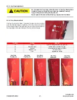
Make appropriate adjustments to equipment. (See 8.2 ADJUSTMENTS on page 39.)

Inspect all welds for wear. Re-weld as necessary.

Check for loose hardware, missing guards, or damaged parts.

Check for damaged or missing safety signs (decals). Replace if necessary.

Touch up all paint nicks and scratches to prevent rusting.

Place the equipment in a dry protected shelter.

Place the equipment flat on the ground.

8.4   RETURNING THE MIXER TO SERVICE 

After the Meyer mixer has been in storage, it is necessary to follow a list of items to return the equipment to service. 

Be sure all shields and guards are in place.

Lubricate the equipment.

Operate equipment; verify all functions operate correctly.

Check for leaks. Repair as needed.

Summary of Contents for F585 2018

Page 1: ...6990633 1 13 Printed in U S A Bobcat Company 2013 FORMULA MIXER Models F585 F700 Mechanical Truck Mount Owner Operator s Manual Parts Book 2018 Model Year Later PB MIXER TR MECH 1 2020 ...

Page 2: ...ys use your serial number when requesting information or when ordering parts HOW TO READ YOUR SERIAL NUMBER Meyer Manufacturing Corporation 674 W Business Cty Rd A Dorchester WI 54425 Phone 1 800 325 9103 Fax 715 654 5513 Email sales meyermfg com Website www meyermfg com Model No Mixer Serial No Date of Purchase Dealership Dealership Phone No Mixer Body Serial Number Model Year Vertical Mixer Mode...

Page 3: ... satisfactorily Any adjustments made MUST be according to specifications defined in this manual DELIVERY CHECK LIST The following check list is an important reminder of valuable information that MUST be passed on to the customer at the time the unit is delivered Check off each item as you explain it to the customer Explain to the customer that pre delivery check list was fully completed Give custo...

Page 4: ...facturing Corporation 4 Formula Mixer Check List Meyer Manufacturing Corporation 674 W Business Cty Rd A Dorchester WI 54425 Phone 1 800 325 9103 Fax 715 654 5513 Email sales meyermfg com Website www meyermfg com ...

Page 5: ...conjunction with your truck chassis manual The formula mixer may be referred to as mixer implement equipment or machine in this manual Manufacturer s Statement Meyer Manufacturing Corporation reserves the right to make improvements in design or changes in specifications at any time without incurring any obligation to owners of units previously sold This supersedes all previous published instructio...

Page 6: ... Ladder STD STD Torque Disconnect PTO s STD STD 2 Speed Electric Shift STD STD Straight Drive STD STD Heavy Duty Gearboxes STD STD DESCRIPTION F585 F700 Side Discharge Door Right Left OPT OPT Rear Discharge Door OPT OPT Slide Tray OPT OPT Magnets OPT OPT Hay Retention Ring OPT OPT Capacity Belt Extension OPT OPT Hardened Knives Additional OPT OPT Tank Liner OPT OPT Baffle Liner OPT OPT ...

Page 7: ...mmendations 20 6 0 PRE OPERATION 21 6 1 STATIC INSPECTION 21 6 2 TRUCK MOUNT SPECIFICATIONS 22 6 3 PTO DRIVELINE 22 6 4 START UP AND SHUT DOWN 22 6 4 1 Start Up 22 6 4 2 Shut Down 23 6 5 OPERATIONAL CHECKS 23 6 5 1 Controls 24 6 6 TRANSPORTING 25 6 6 1 Brake Information 25 6 7 OPTIONAL EQUIPMENT 26 6 7 1 Digital Scale Indicator 26 7 0 OPERATION 27 7 1 GENERAL 27 7 1 1 Cutout Clutch 28 7 1 2 Materi...

Page 8: ...39 8 2 2 Auger Timing 39 8 2 3 PTO Cutout Clutch Connection 39 8 2 4 Knives 40 8 2 4 1 Knife Removal 40 8 2 4 2 Adding Knives 40 8 2 4 3 Knife Placement 40 8 2 4 4 Knife Position 40 8 2 4 5 Replacing Damaged or Worn Knives 40 8 2 5 Hay Stop Adjustment 41 8 2 5 1 Hay Stop Lock Bolt 41 8 3 STORING THE MIXER 42 8 4 RETURNING THE MIXER TO SERVICE 42 8 5 REPLACEMENT PARTS 43 9 0 PARTS 45 ELECTRICAL 45 ...

Page 9: ...N 18VM0585230 71 LOWER GEARBOX SN 18VM 0585230 0700212 LATER 72 UPPER GEARBOX SN 18VM 0585230 0700212 LATER 74 1800 SERIES PLANETARY 119 18 13 92 1 76 HOSE FITTING HYDRAULIC SYSTEM 78 OPTIONAL EQUIPMENT 80 HAY RETAINING RING 80 8 CAPACITY EXTENSION 81 SIDE DISCHARGE SLIDE TRAY 82 SLIDE TRAY HYDRAULIC SCHEMATIC 84 DUAL SLIDE TRAY HYDRAULIC SCHEMATIC 85 REMOTE SCALE MOUNT 86 TANK MAGNET 88 10 0 SPEC...

Page 10: ...Meyer Manufacturing Corporation 10 PB MIXER TR MECH ...

Page 11: ...out charge for either parts or labor during the first 1 year from purchase date to the original retail customer B In addition to the above basic warranty Meyer Mfg Corp will repair or replace F O B Dorchester WI as Meyer Mfg Corp elects i Any part of the following which is defective in material or workmanship not neglect to recommended use and service with a pro rated charge for parts only not lab...

Page 12: ...Meyer Manufacturing Corporation 12 PB MIXER TR MECH ...

Page 13: ... warn you of hazards and must be read and observed closely Danger Warning Caution and instructional decals and plates are placed on the equipment to protect anyone working on or around this equipment as well as the components of the equipment All personnel operating or maintaining this equipment must familiarize themselves with all Danger Warning Caution and instructional decals and plates This sy...

Page 14: ...ment is in motion Inspect when first delivered and regularly thereafter that all connections and bolts are tight and secure before operating Know how to stop operation of the equipment before starting it Make certain everyone is clear of the equipment before applying power Keep hands feet and clothing away from moving parts Loose or floppy clothing should not be worn by the operator Observe all ap...

Page 15: ...fety Precautions For Hydraulic System Check hydraulic tubes hoses and fittings for damage and leakage Never use hands to check for leaks Hydraulic tubes and hoses must be properly routed and have adequate support and secure clamps Tighten or replace any parts that show leakage Always clean fluid spills Do not use gasoline or diesel fuel for cleaning parts Use commercial nonflammable solvents ...

Page 16: ...afety signs on the equipment and in this manual Keep all safety signs clean and replace any damaged or missing safety signs before operating the equipment Do Not remove any safety signs Safety signs are for operator protection and information FRONT OF MIXER PART NO 46 0001 211 1 1 ...

Page 17: ...1 800 325 9103 PB MIXER TR MECH 17 www meyermfg com FRONT OF MIXER 1 2 3 4 PART NO 46 0001 213 1 PART NO 46 8500 7 2 3 PART NO 46 0001 35 4 PART NO 46 0001 22 ...

Page 18: ...REAR OF MIXER 1 2 3 3 4 4 PART NO 46 0001 210 1 PART NO 46 0001 213 3 WARNING OIL INJECTION HAZARD RELIEVE PRESSURE BEFORE SERVICING DO NOT CHECK WITH HANDS IF INJURED SEEK EMERGENCY MEDICAL ATTENTION 46 8500 7 1 PART NO 46 8500 7 2 4 PART NO 46 0001 208 ...

Page 19: ...1 800 325 9103 PB MIXER TR MECH 19 www meyermfg com 1 PART NO 46 0001 211 1 UNDER MIXER PART NO 46 0001 212 Located under mixing tub Located under mixer belting ...

Page 20: ...s power source Ensure that this machine is level set the parking brake and chock the wheels Disconnect electricity block moveable parts release or block spring energy release pressure from hydraulic and pneumatic lines and lower suspended parts to a resting position 5 Test Do a complete test and personally double check all of the above steps to verify that all of the power sources are actually dis...

Page 21: ...l all operators have read and understand all of the instructional materials in this Operator s And Parts Manual and have been properly trained in its intended usage Verify that the equipment is securely fastened to the truck Verify that all electrical hydraulic connections and bolts hardware are tight and securely fastened before operating the equipment Always keep all shields and guards in place ...

Page 22: ...ore performing machine service adjusting maintaining or clearing an obstruction from this machine Refer to section 5 3 SHUTOFF LOCKOUT POWER Do not operate without PTO guard on implement Maintain PTO drive shaft guard tubes in good operating condition Replace them if damaged and not turning freely Failure to heed may result in serious personal injury or death DO NOT allow anyone to operate service...

Page 23: ...ot 7 Check all hydraulic components for leaks 8 Adjust and lubricate equipment as needed See 8 1 LUBRICATION See 8 2 ADJUSTMENTS Shutoff and lockout power before performing machine service adjusting maintaining or clearing an obstruction from this machine Refer to section 5 3 SHUTOFF LOCKOUT POWER DO NOT allow anyone to operate service inspect or otherwise handle this mixer until all operators hav...

Page 24: ...utton on the joystick turns the conveyor on and off Toggling the rear door momentary switch forward Item 5 lowers the rear door Toggling the rear door momentary switch back Item 6 raises the rear door The light switch selected forward Item 7 turns the lights on and selected back Item 8 turns the lights off The two speed switch selected forward Item 9 shifts the gearbox to high and selected back It...

Page 25: ...lights and reflectors are installed and working Shutoff and lockout power before performing machine service adjusting maintaining or clearing an obstruction from this machine Refer to section 5 3 SHUTOFF LOCKOUT POWER Place safety stands under frame and chock wheels before working on tires or chassis Maintain wheel bolts at torque as recommended in the manual If equipped with brakes maintain prope...

Page 26: ...efer to scale indicator Item 1 manufacturer s operator manual for operation and maintenance NOTE Some scale drift may occur after the scale is turned on but should level out within 10 to 15 minutes Temperature changes may also cause some drifting See your Digi Star manual for additional scale information 1 ...

Page 27: ...onal materials in this Operator s And Parts Manual and have been properly trained in its intended usage Before operating the mixer look in all directions and make sure no bystanders especially small children are in the work area Do not climb or step onto the platform or ladder before the parking brake has been applied Turn on level ground Slow down when turning Go up and down slopes not across the...

Page 28: ...ch will either re engage upon shut down of the PTO or just before it comes to a complete stop 7 1 2 Material Some feed materials will need to be processed alone in the mixer before they can be efficiently mixed with other feed materials Large square or round bales of alfalfa Large square or round bales of high moisture content Large square or round bales of long mixed grasses wheat or oat hay and ...

Page 29: ...A MIXER GROSS WEIGHT MATERIAL ESTIMATED WEIGHT PER CUBIC FOOT MODEL LBS MATERIAL LBS CU FT F585 80 000 Soybeans 47 lbs F700 80 000 Cotton Seed Dry 20 lbs Corn Shelled 45 lbs Corn Silage 30 lbs Haylage 20 lbs DO NOT ENTER MIXER CHAMBER WHILE MIXER IS RUNNING Shutoff and lockout power before performing machine service adjusting maintaining or clearing an obstruction from this machine Refer to sectio...

Page 30: ...ng from a raised bay or platform adopt the necessary measures safety rails etc to avoid people or equipment from falling into the machine Load all ingredients as quickly as possible Allow a final mix time of 3 7 minutes or whenever the load looks consistently mixed Never load long stem bales last They will not be processed or mixed into the ration and may cause unloading difficulties or spillage D...

Page 31: ...he discharge path NOTE The mixer PTO MUST be stopped before shifting the 2 speed gearbox to prevent damage to the gearbox 6 The 2 speed gearbox can be shifted into HIGH during the unloading process Stop the PTO prior to shifting This will help remove any feed remaining on the augers and assist in keeping an even feed flow until the mixer is empty NOTE For Truck Mounted Models do not operate above ...

Page 32: ...nside Adjust hay stops to a less aggressive or neutral position See Section 8 2 5 Adjust knives to a less aggressive position See Section 8 2 4 If spillage still occurs the optional side extensions or hay retention ring may need to be installed Requiring High Horsepower Reduce load size Adjust hay stops to a less aggressive or neutral position See Section 8 2 5 The load size may need to be reduced...

Page 33: ... daily to prevent abnormal component wear Add new oil to the reservoir tank Item 1 if the oil level is not at the oil reservoir mark Check the 2 speed gearbox oil level daily to prevent abnormal component wear Add new oil to the 2 speed gearbox if the oil level is not halfway up the sight glass Check the remote hydraulic power unit oil level With all cylinders collapsed fill within 1 2 of the oil ...

Page 34: ...ne NOTE Shielding has been removed for illustration purposes only Grease all driveline bearings Item 1 8 1 3 Every 40 hours Oil Door Pivots Item 2 8 1 4 50 hours First oil change in the planetaries 2 speed gearbox and front gearboxes See pages 37 38 1 1 Rear Discharge Door 2 ...

Page 35: ...de Item 4 8 1 5 Annually or Every 500 hours Whichever Is First Change oil in the 2 speed gearbox See page 38 Check condition of the external seals and make sure there are no leaks on planetaries Change oil in both Superior Benzi version front driveline gearboxes 118 VM 0014 55 All Automotive Drivelines Double Universal Joint 3 4 ...

Page 36: ...ER TR MECH 8 1 6 Annually or Every 2000 hours Whichever Is First Change oil in the planetaries See page 37 8 1 7 Every 5000 hours Replace all planetary bearings Change external planetary O rings Check the extent of wear on all planetary gears ...

Page 37: ...Item 1 Connect oil pump to lower hose and fill with oil until the catch basin fills with approximately 2 quarts of oil Discard this oil if it is dirty Reattach the lower hose Item 1 with the hose clamp Bolt the reservoir back in place Fill the reservoir to the oil level mark and reinstall the cap Item 3 Inspect the reservoirs breather make sure it is not plugged and check for leaks PLANETARY LUBRI...

Page 38: ...her 8 1 8 3 Superior Benzi Front Driveline Gearbox Run mixer to warm gearbox oil Remove belting Disconnect drive shafts Left PTO Drive U joint will slide off gearbox shaft while removing lower gearbox Right PTO Drive Remove chain coupler between both gearboxes Unbolt bottom gearbox and remove Unbolt upper gearbox support 2 SPEED GEARBOX LUBRICATION SPECIFICATIONS Model Part Number Description Oil ...

Page 39: ...through the hub being sure the bolt is falling into the groove on the splined shaft Torque tight using a metric size M16 6 point socket and torque down to 75 ft lbs A M16 6 POINT METRIC SOCKET MUST BE USED AS ROUNDING OF HEXAGON BOLT AND INACCURACY OF TORQUE SETTINGS COULD OCCUR If removal of the M 16 hexagon bolt is necessary use the same M 16 6 point socket and loosen bolt 1 2 turn Insert a 1 4 ...

Page 40: ...on they tend to move the long stem hay and lighter bulky materials best in the early stages of processing and mixing This setting may result in feed spillage in certain materials Knives placed in this setting are very aggressive in processing feed and will also cause an increase in horsepower requirement In Position When the knives are in the in position they will slow down the long stem hay and l...

Page 41: ...auger Position Setting Material A High Light and bulky material dry grasses B Medium High Alfalfa bales and other forages C Neutral Unrestrained movement of feed D Medium Low Heavier rations E Low Aggressive cutting Do not adjust the hay stops while the mixer is running Moving feed inside the mixer can make the hay stop move suddenly causing injury to the person making the adjustment Never operate...

Page 42: ...ge Repair and replace components as necessary Make appropriate adjustments to equipment See 8 2 ADJUSTMENTS on page 39 Inspect all welds for wear Re weld as necessary Check for loose hardware missing guards or damaged parts Check for damaged or missing safety signs decals Replace if necessary Touch up all paint nicks and scratches to prevent rusting Place the equipment in a dry protected shelter P...

Page 43: ...y friendly and dispose of any waste materials properly Recycle when appropriate Before servicing this equipment ensure that all personnel including family members are familiar with the equipment and the safety hazards that are present along with the safety practices that should be observed while working in this equipment Inspect the truck chassis all safety shielding safety signs and safety lighti...

Page 44: ...Meyer Manufacturing Corporation 44 PB MIXER TR MECH ...

Page 45: ...6 Oval Red LED Light 585 700 3 56 0130 2 2 Right Left Light Pigtail Lead 585 700 4 56 0130 1 1 Y Harness Less Light Plug Leads 585 700 5 56 0037 AR 16GA 4 Wire Trailer Cable By The Foot 585 700 156 C 6FL TO 1 1 6 Contact Connector 585 700 156 P 1 2 Green Cavity Plug 585 700 156 S 18 16 1 4 Green Cable Seal 585 700 156 T 16 14 F 1 4 Female Terminal Ends 585 700 3 1 2 2 1 3 5 4 ...

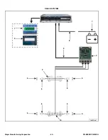
Page 46: ...Meyer Manufacturing Corporation 46 PB MIXER TR MECH SCALE SYSTEM PBMTR 007 4 7 8 6 5 6 5 6 9 1 2 6 5 5 10 3 ...

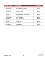
Page 47: ...12 0002 2 Truck Frame Mount 585 700 4 58 0020 1 6 Point Mobil J Box 585 700 58 0008 1 6 Point Mobil J Box With Monitor Cable 585 700 5 M9 1 8 0001 4 DB Bar Mount 585 700 881 7510 2 5Z 8 3 4 10 x 2 1 2 Bolt 585 700 6 58 0034 WT 4 2 875 x 14 Load Cell 585 700 7 See Page 48 50 1 12V Power Cord Assembly 585 700 8 58 0043 1 10 Power Cord 585 700 9 58 0029 1 Junction Box To Monitor Cable 30 585 700 10 M...

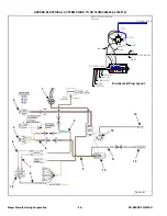
Page 48: ...SPEED ELECTRICAL SYSTEM PRIOR TO SN 18VM 0585235 0700212 FM 165 B1 9 14 13 11 12 10 8 7 5 4 2 6 3 1 15 7 8 7 6 2 5 3 2 7 1 2 5 7 6 2 5 3 2 7 7 6 2 5 3 2 7 2 2 5 7 1 2 2 7 5 1 5 1 2 5 2 5 2 7 8 7 2 7 7 2 1 2 7 8 7 7 8 2 7 6 2 5 3 2 7 Enclosure Wiring Layout ...

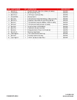
Page 49: ...585 700 6 56 0400 1 1 2 Speed Optional Bunk Light Wiring Harness 585 700 7 56 0407 1 12V Hydraulic Pump Red Battery Cable Assembly 585 700 8 56 0405 1 12V Hydraulic Pump Harness Assembly 585 700 9 56 0205 1 Junction Power Cord Assembly 585 700 10 56 0215 1 Terminal Enclosure Assembly 585 700 11 56 0404 1 2 Speed Actuator Power Cord Assembly 585 700 12 56 0200 3 1 Normally Open Relay 585 700 13 See...

Page 50: ...IXER TR MECH 2 SPEED ELECTRICAL SYSTEM SN 18VM 0585235 0700212 LATER FM 165 B2 9 14 13 11 12 10 8 7 5 4 2 6 3 1 15 7 6 2 5 3 5 2 5 2 7 8 7 2 7 7 2 2 5 7 1 2 2 7 5 1 5 1 2 5 2 72 352 6 7 8 72 352 6 7 1 2 5 72 352 6 7 7 Enclosure Wiring Layout ...

Page 51: ...585 700 6 56 0400 1 1 2 Speed Optional Bunk Light Wiring Harness 585 700 7 56 0407 1 12V Hydraulic Pump Red Battery Cable Assembly 585 700 8 56 0405 1 12V Hydraulic Pump Harness Assembly 585 700 9 56 0205 1 Junction Power Cord Assembly 585 700 10 56 0281 1 Terminal Enclosure Assembly 585 700 11 56 0404 1 2 Speed Actuator Power Cord Assembly 585 700 12 56 0200 3 1 Normally Open Relay 585 700 13 See...

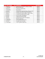
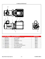
Page 52: ...ssembly 585 700 2 155 M 0007 5 1 Filter Screen 585 700 3 155 M 0007 1 1 Plastic Reservoir Tank 585 700 4 155 M 0007 4 1 Hose Clamp 585 700 5 155 M 0007 2 1 12V DC Motor 585 700 6 155 M 0007 6 1 12V DC Solenoid Switch 585 700 7 155 M 0007 7 1 Motor Solenoid Connecting Strap 585 700 8 155 M 0007 8 1 Control Wire Assembly 585 700 9 155 M 0007 9 1 Breather Filler Plug 585 700 1 8 5 7 6 9 3 4 2 ...

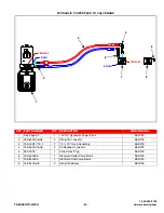
Page 53: ...0 2 155 6400 06 06 2 Straight Connector 585 700 3 155 04R17 19 1 2 1 4 x 19 Hose Assembly 585 700 4 155 6500 06 06 2 90 Degree Connector 585 700 5 955 0009 1 Hollow Hex Plug 585 700 6 155 M 0006 1 Standard Outlet Valve Bank 585 700 7 155 M 0005 1 Standard Inlet Valve Bank 585 700 8 155 6400 6 8 2 Straight Adapter 585 700 5 8 6 6 5 3 5 8 6 6 5 3 1 5 8 7 5 1 5 8 7 5 3 1 5 6 7 8 4 2 ...

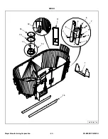
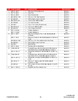
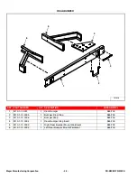
Page 54: ...Meyer Manufacturing Corporation 54 PB MIXER TR MECH MIXER MIXER 585 700 8 9 6 3 7 10 5 2 4 1 13 14 17 15 16 12 11 ...

Page 55: ...18VM 0585208 0700203 585 700 M6 1 7 0016 1 Rear Door Deflector SN 18VM 0585208 0700203 Later 585 700 803 3816 1 25Z 5 3 8 16 x 1 1 4 Flat Head Socket Cap Screw 585 700 815 3816 Z 5 3 8 16 Nylon Insert Lock Nut 585 700 13 49 0262 2 Belt Skirting 585 700 14 M2 1 5 0006 2 Planetary Mount Weldment 585 700 15 VAM ASK KIT 1 Complete Auger Seal Installation Kit With Weld On Seal Plate Prior to SN 18VM 05...

Page 56: ...EL 1 M13 1 7 0001 1 Rear Bumper 585 700 2 M13 1 12 0005 1 Bumper Drop Step 585 700 3 M13 1 12 0006 1 Bumper Step 585 700 4 M13 1 12 0004 1 Rear Bumper Step Insert 585 700 5 M13 1 12 0003 1 Right Rear Bumper Mount Weldment 585 700 6 M13 1 12 0002 1 Left Rear Bumper Mount Weldment 585 700 FM 050 2 3 1 6 5 4 ...

Page 57: ...1 800 325 9103 PB MIXER TR MECH 57 www meyermfg com ...

Page 58: ...Meyer Manufacturing Corporation 58 PB MIXER TR MECH DOOR FM 100 8 3 1 2 6 11 9 5 4 7 10 ...

Page 59: ... 18 585 700 6 M6 1 8 0004 1 Left Door Frame Guide Assembly 585 700 7 M6 1 8 0008 1 Door Link Arm Assembly 585 700 851 1008 3Z 2 Machine Bolt 1 8 x 3 585 700 815 1008 Z 2 Lock Nut 1 8 Nylon Insert 585 700 8 M6 1 8 0009 1 Rear Door Link Pivot Pin Assembly 585 700 M6 1 7 0010 1 Right Door Pivot Pin Assembly 585 700 M6 1 7 0011 1 Left Door Pivot Pin Assembly 585 700 851 3816 1 25Z 1 3 8 16 x 1 1 4 Mac...

Page 60: ...0 2 155 04R17 251 1 1 1 4 x 251 Hose Assembly 585 700 3 155 2 5 12 1 125 1 1 2 1 2 x 12 x 1 1 8 Hydraulic Cylinder 585 700 4 155 6400 6 8 2 Straight Adapter 585 700 5 155 6801 6 8 2 90 Degree Adapter 585 700 6 155 M 0001 1 Closed Center Section Door Cylinder Valve Bank 585 700 5 5 225 2 1 5 5 225 83 167 876 3 8 7 5 5 520 2 67 51 66 66 0 167 876 3 8 7 3853 5 520 2 67 51 66 66 0 MEYER M 6 1 5 4 2 3 ...

Page 61: ...2 155 04R17 102 1 1 1 4 x 10² Hose Assembly 585 700 3 155 2 5 12 1 125 1 1 2 1 2 x 12 x 1 1 8 Hydraulic Cylinder 585 700 4 155 6400 6 8 2 Straight Adapter 585 700 5 155 6801 6 8 2 90 Degree Adapter 585 700 6 155 M 0001 1 Closed Center Section Door Cylinder Valve Bank 585 700 167 876 3 8 7 7 5 520 2 67 51 66 66 0 167 876 3 8 7 52 1 5 520 2 67 51 66 66 0 225 2 1 225 83 MEY 6 1 5 4 2 3 ...

Page 62: ...Meyer Manufacturing Corporation 62 PB MIXER TR MECH AUGER PB 19_004 6 1 2 7 8 3 5 9 4 10 ...

Page 63: ...8 11 x 2 Carriage Bolt Zinc Square Hole Auger Flighting 585 700 880 6311 2 5Z 1 per 5 8 11 x 2 Carriage Bolt Zinc Square Hole Auger Flighting 585 700 886 6311 Z 2 per 5 8 11 Center Lock Nut 585 700 5 M5 1 8 0007 2 Auger Kicker Nut Holder Weldment 585 700 6 M11 1 0040 K 10 Mixer Knife Assembly Includes Knives Backers Hardware 585 700 M11 1 0041 K 10 Mixer HD Knife Assembly Includes Knives Backers H...

Page 64: ...Meyer Manufacturing Corporation 64 PB MIXER TR MECH DRIVELINE FM 160 A 6 1 3 2 4 5 7 9 10 9 5 8 11 11 13 15 15 19 18 17 16 14 12 ...

Page 65: ...585 700 12 See Page 66 1 Front Gearbox Right PTO Driveline Mount 585 700 See Page 68 1 Front Gearbox Left PTO Driveline Mount 585 700 13 VAML 2SP BJSR KIT 1 2 Speed Shift Rod Kit Without Springs 585 700 VAML 2SP BJSRS KIT 1 2 Speed Shift Rod Kit With Springs 585 700 14 814 5612 Z 1 9 16 12 Indented Lock Nut SN 18VM 0585224 0700207 Later 585 700 15 VAML 2SP BJSRS KIT 1 2 Speed Shift Rod Kit With Sp...

Page 66: ...Meyer Manufacturing Corporation 66 PB MIXER TR MECH RIGHT SIDE PTO GEARBOX DRIVELINE MOUNT 7 1 8 6 5 2 3 4 8 ...

Page 67: ...N 18VM 0585230 0700212 Later 585 700 5 M9 1 5 0011 1 Gearbox Mount Weldment Prior to SN 18VM0585230 585 Call 1 800 325 9103 1 Gearbox Mount Weldment Prior to SN 18VM0700212 700 M9 1 5 0014 1 Gearbox Mount Weldment SN 18VM 0585230 0700212 Later 585 700 6 M9 1 5 0011 3 1 Gearbox Mount Plate Prior to SN 18VM0585230 585 Call 1 800 325 9103 1 Gearbox Mount Prior to SN 18VM0700212 700 925 0550 6 1 Gearb...

Page 68: ...Meyer Manufacturing Corporation 68 PB MIXER TR MECH LEFT SIDE PTO GEARBOX DRIVELINE MOUNT 7 8 6 5 3 9 4 8 2 1 ...

Page 69: ... 5 M9 1 5 0012 1 Gearbox Mount Weldment Prior to SN 18VM0585230 585 Call 1 800 325 9103 1 Gearbox Mount Weldment Prior to SN 18VM0700212 700 M9 1 5 0015 1 Gearbox Mount Weldment SN 18VM 0585230 0700212 Later 585 700 6 M9 1 5 0011 3 1 Gearbox Mount Plate Prior to SN 18VM0585230 585 Call 1 800 325 9103 1 Gearbox Mount Prior to SN 18VM0700212 700 925 0550 6 1 Gearbox Mount SN 18VM 0585230 0700212 Lat...

Page 70: ...n Shaft Gear w Bearings Cups Seal Retaining Ring Assembly 4 619 0010 4 Cross Shaft Gear Assembly 1 35 1 5 19 0029 7 Bearing Cone 1 3 4 6 19 0029 8 Bearing Cup 7 19 0029 16 Bearing Cone 8 19 0029 9 Seal 1 3 4 9 19 0029 11 Retaining Ring 1 3 4 10 19 0016 11 Bolt 3 8 16 x 2 1 4 SHCS 11 19 0016 5 Plug 1 2 NPT 12 19 0024 17 Bushing 1 2 to 1 8 NPT 13 19 0002 17 5 PSI Vent Plug 2 13 1 4 5 6 8 11 8 12 10 ...

Page 71: ...Assembly 1 35 1 4 619 0010 4 Cross Shaft Gear Assembly 1 35 1 5 19 0029 7 Bearing Cone 1 3 4 6 19 0029 8 Bearing Cup 7 19 0029 5 Bearing Cone 8 19 0029 6 Bearing Cup 9 19 0029 9 Seal 1 3 4 10 19 0029 11 Retaining Ring 1 3 4 11 19 0016 11 Bolt 3 8 16 x 2 1 4 SHCS 12 19 0016 5 Plug 1 2 NPT 13 19 0024 17 Bushing 1 2 to 1 8 NPT 14 19 0002 17 5 PSI Vent Plug 15 19 0029 16 Bearing Cup 2 1 5 6 9 12 7 8 6...

Page 72: ...yer Manufacturing Corporation 72 PB MIXER TR MECH LOWER GEARBOX SN 18VM 0585230 0700212 LATER 3 2 17 20 16 6 7 19 12 15 16 17 4 8 9 10 1 11 5 18 22 23 30 21 35 18 32 31 24 25 31 32 33 34 26 29 12 15 26 29 ...

Page 73: ...1 1 Taper Bearing 12 119 B 12 2 Shim 13 119 B 13 2 Shim 14 119 B 14 2 Shim 15 119 B 15 2 Shim 16 119 B 16 2 Washer 17 119 B 17 2 Circlip 18 119 B 18 2 Seal Ring 19 119 B 19 1 Roller Bearing 20 119 B 20 1 Seal Ring 21 119 B 21 1 Round Shaft 22 119 B 22 1 Circlip 23 119 B 23 1 Washer 24 119 B 24 1 Bevel Gear 25 119 B 25 1 Spacer 26 119 B 26 2 Shim 27 119 B 27 2 Shim 28 119 B 28 2 Shim 29 119 B 29 2 ...

Page 74: ...yer Manufacturing Corporation 74 PB MIXER TR MECH UPPER GEARBOX SN 18VM 0585230 0700212 LATER 3 2 17 20 16 6 7 19 12 15 16 17 4 8 9 10 1 11 5 18 22 23 30 21 35 18 32 31 24 25 26 29 31 32 33 34 26 29 12 15 ...

Page 75: ...1 1 Taper Bearing 12 119 B 12 2 Shim 13 119 B 13 2 Shim 14 119 B 14 2 Shim 15 119 B 15 2 Shim 16 119 B 16 2 Washer 17 119 B 17 2 Circlip 18 119 B 18 2 Seal Ring 19 119 B 19 1 Roller Bearing 20 119 B 20 1 Seal Ring 21 119 B 36 1 Round Shaft 22 119 B 22 1 Circlip 23 119 B 23 1 Washer 24 119 B 24 1 Bevel Gear 25 119 B 25 1 Spacer 26 119 B 26 2 Shim 27 119 B 27 2 Shim 28 119 B 28 2 Shim 29 119 B 29 2 ...

Page 76: ...Meyer Manufacturing Corporation 76 PB MIXER TR MECH 1800 SERIES PLANETARY 119 18 13 92 1 FM 175 1 2 6 3 12 8 3 4 10 11 5 9 7 ...

Page 77: ...al 2 119 P RR 5 1 O Ring 3 119 P RR 6 2 Oil Seal 4 119 P RR 7 1 O Ring 5 119 P RR 13 1 Shaft Protection Shield 6 119 P RR 14 2 Thickness Kit 7 119 P RR 15 1 Cover 8 119 P RR 16 2 Thickness Kit 9 119 P RR 17 1 Cover 10 119 P RR 18 1 Snap Ring 11 851 M5 8 10 YZ 4 Cap Screw 12 851 M10 1 5 25 Z 6 Machine Bolt ...

Page 78: ...acturing Corporation 78 PB MIXER TR MECH HOSE FITTING HYDRAULIC SYSTEM Planetary Gearbox 3 8 5 7 4 6 11 12 13 1 10 2 Use 48 0081 Synthetic ISO220 or Equivalent For Planetary Gearboxes 9 9 7 1 12 13 FRONT REAR 6 11 ...

Page 79: ...lastic Tank With Vented Cap 585 700 6 55 0403 2 1 2 x 1 4 BRS 90 Elbow 585 700 7 55 0404 2 1 2 x 3 8 BRS MA Barb Hose 585 700 8 55 0405 2 1 2 x 3 8 BRS MA Barb Hose 585 700 9 55 0307 2 Breather Vent 3 8 Pipe x 11 16 Hex 150 PSI 585 700 10 See Page 76 2 1800 Planetary Gearbox 13 92 1 Ratio 1 75 20 SPL 585 700 11 155 PB4 4 2 4NPT FEMx4BSPP Adapter With BSP Bonded Seal 585 700 12 155 PB12 12 2 12NPT ...

Page 80: ...ON MIXER MODEL 1 M4 1 5 0001 2 Hay Retention Ring End Weldment 585 M4 1 7 0001 2 Hay Retention Ring End Weldment 700 2 M4 1 7 0002 2 Hay Retention Ring Side Weldment 585 700 NS 851 5013 1 25Z AR 1 2 13 x 1 1 4 Bolt 585 700 NS 805 0050 Z AR 1 2 Flat Washer 585 700 NS 810 5013 Z AR 1 2 Spin Lock Nut 585 700 FM 240 2 1 1 2 ...

Page 81: ...city Extension 453 x 8 x 45 FT 585 M11 7 0001 1 8 Capacity Extension 453 x 8 x 46 FT 700 805 0038 Z 4 3 8 Flat Washer 585 700 815 3816 Z 2 3 8 16 Nylon Insert Lock Nut 585 700 851 3816 1 25Z 2 3 8 16 x 1 1 4 Grade 5 Machine Bolt 585 700 2 M4 1 8 0006 38 Belt Extension Mounts 585 700 805 0050 Z 38 1 2 Flat Washer 585 700 814 5013 Z 38 1 2 13 Indented Lock Nut 585 700 851 5013 1 5Z 38 1 2 13 x 1 1 2...

Page 82: ...Meyer Manufacturing Corporation 82 PB MIXER TR MECH SIDE DISCHARGE SLIDE TRAY FM 125A 2 1 4 5 6 7 3 ...

Page 83: ...810 3118 Z 16 5 16 18 Spin Lock Nut 585 700 3 M3 1 12 0008 1 Chute Pivot Rod 1 x 47 3 4 585 700 4 155 2 8 1 125 1 1 2 x 8 x 1 1 8 Hydraulic Cylinder 8 SAE Ports 585 700 5 33 0309 1 Cylinder Pin Spacer 585 700 6 808 1 1 5 10 Z 1 10GA 1 ID x 1 1 2 OD MB 585 700 7 M3 1 4 0044 1 Slide Tray Deflector Belting 585 700 805 0038 Z 3 3 8 Flat Washer 585 700 815 3816 Z 3 3 8 16 Nylon Insert Lock Nut 585 700 ...

Page 84: ...00 2 155 2 8 1 125 1 1 2 x 8 x 1 1 8 Hydraulic Cylinder 585 700 3 155 04R17 173 1 1 1 4 x 173 Hose Assembly 585 700 4 155 04R17 185 1 1 1 4 x 185 Hose Assembly 585 700 5 155 6400 6 8 2 Straight Adapter 585 700 6 155 M 0002 1 Cylinder Valve Bank 585 700 6 75 2 1 6 75 83 167 876 3 8 7 8 5 520 2 67 51 66 66 0 167 876 3 8 7 5 1 5 520 2 67 51 66 66 0 MEYER MFG 6 1 5 4 3 2 ...

Page 85: ...ose Assembly 585 700 4 155 04R17 144 1 2 1 4 x 144 Hose Assembly 585 700 5 155 6400 6 8 2 Straight Adapter 585 700 6 155 M 0002 1 Cylinder Valve Bank 585 700 7 155 04R17 70 1 2 1 4 x 70 Hose Assembly 585 700 8 155 2603 06 06 06 2 Tee Connector 585 700 9 155 6500 06 06 2 90 Degree Connector 585 700 5 1 5 5217 7 6 75 1 5 5 7 6 1 2 5 7 6 3 8 6 7 8 7 6 1 7 8 3 7 6 2 0 2 5 0 6 6 6 6 1 5 6 7 8 7 6 1 7 8...

Page 86: ...Meyer Manufacturing Corporation 86 PB MIXER TR MECH REMOTE SCALE MOUNT FM 255 A 4 3 5 6 1 2 8 8 6 7 9 8 10 ...

Page 87: ...mote Scale Mount Bracket 585 700 3 M9 1 10 0003 1 Remote Scale Mount Belt Gusset 585 700 4 58 0010 407227 1 RD2500V Remote Display Kit W 25 Cable Visor 585 700 58 0010 405200 1 RD4000 Remote Display Kit W 33 Cable Visor 585 700 5 815 2520 Z 4 1 4 20 Nylon Insert Lock Nut 585 700 6 851 3816 1Z 8 3 8 16 x 1 Grade 5 Machine Bolt 585 700 7 805 0038 Z 6 3 8 Flat Washer 585 700 8 810 3816 Z 8 3 8 Spin L...

Page 88: ... QTY DESCRIPTION MIXER MODEL 0 VAM TM KIT 1 Tank Magnet Install Kit 585 700 1 33 0028 2 1 2 13 Handle Nut 585 700 2 M11 10 0012 2 1 Tank Magnet Door Weldment 585 700 3 826 5013 2 1 2 13 Jam Nut 585 700 4 850 5013 1 75Z 2 1 2 13 x 1 3 4 Carriage Bolt 585 700 TANK MAGNET 1 3 2 1 3 4 ...

Page 89: ...s Option Sensitive 12 020 N A Maximum Net Load lbs 19 410 22 800 Auger Qty 2 2 Auger Diameter 88 88 Auger Speed standard high speed 27 40 RPM 27 40 RPM Auger Upper Flighting Thickness 5 8 5 8 Auger Lower Flighting Thickness 5 8 5 8 Auger Knives adjustable per auger 5 6 Planetary Drive straight drive straight drive PTO Drive 1800 RPM 1800 RPM Drive Protection torque disconnect torque disconnect Dis...

Page 90: ...Meyer Manufacturing Corporation 90 PB MIXER TR MECH ...

Page 91: ...IAL NO ____________________________________ DATE SERVICE PERFORMED DATE SERVICE PERFORMED Manufactured by Meyer Manufacturing Corporation 674 W Business Cty Rd A Dorchester WI 54425 Phone 1 800 325 9103 Fax 715 654 5513 Email sales meyermfg com Website www meyermfg com ...

Page 92: ...Meyer Manufacturing Corporation 674 W Business Cty Rd A Dorchester WI 54425 Phone 1 800 325 9103 Fax 715 654 5513 Email sales meyermfg com Website www meyermfg com ...

Reviews: