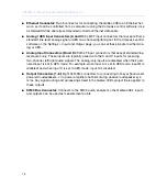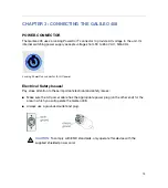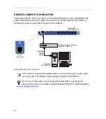
CHAPTER 2: GALILEO 408 FEATURES AND FUNCTIONS
16
GALILEO 408 FRONT PANEL
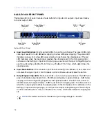
The Galileo 408 front panel includes mute buttons for inputs and outputs, input level indica-
tors, and output LEDs.
■
Input Level Indicators:
Multi-segment LEDs for each input channel. The green LEDs indi-
cate input levels from –80 dB below clipping to a few dB below clipping. The yellow LED
indicates a range from a few dB below clipping to just below the clipping level. The red
LED indicates when the input signal reaches the clipping level. In the Compass control
software on the Settings > Input and Output page, you can set the Input Voltage Range for
each input to 26 dBu (15.5 V rms) or +20 dBu (7.75 V rms), which determines the
clipping levels.
■
Input Mute Buttons:
One for each input channel, allowing the channels to be muted and
unmuted. Muting an input in the Compass control software also activates the button.
■
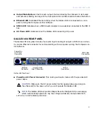
Output Signal / Clip LEDs:
Multi-color LEDs, one for each output channel. The LED turns
green to indicate output levels from –85 dB below clipping to approximately –5 dB below
clipping, with the LED glowing brighter as the signal increases. The LED turns amber to
indicate levels from approximately –5 dB to just below the clipping level. The LED turns red
when the output signal reaches the clipping level. In the Compass control software on the
Settings > Input and Output page, you can set the Output Voltage Range for each output
to 26 dBu (15.5 V rms) or +20 dBu (7.75 V rms), which determines the clipping lev-
els.
NOTE:
The default and recommended Output Voltage Range is +26 dBu.
Galileo 408 Front Panel
INPUT
OUTPUT
1
2
3
4
5
6
7
8
SIGNAL / CLIP
MUTE
Input Mute
Buttons
Input Level
Indicators
Output Mute
Buttons
Output Signal /
Clip LEDs
SIM 3
LED
Ethernet
LED
AC Power
LED
Summary of Contents for Galileo 408
Page 10: ...CONTENTS x...
Page 14: ...CHAPTER 1 INTRODUCTION 14...
Page 26: ...CHAPTER 3 CONNECTING THE GALILEO 408 26...
Page 30: ...APPENDIX A SPECIFICATIONS 30...
Page 31: ......

