12(19)
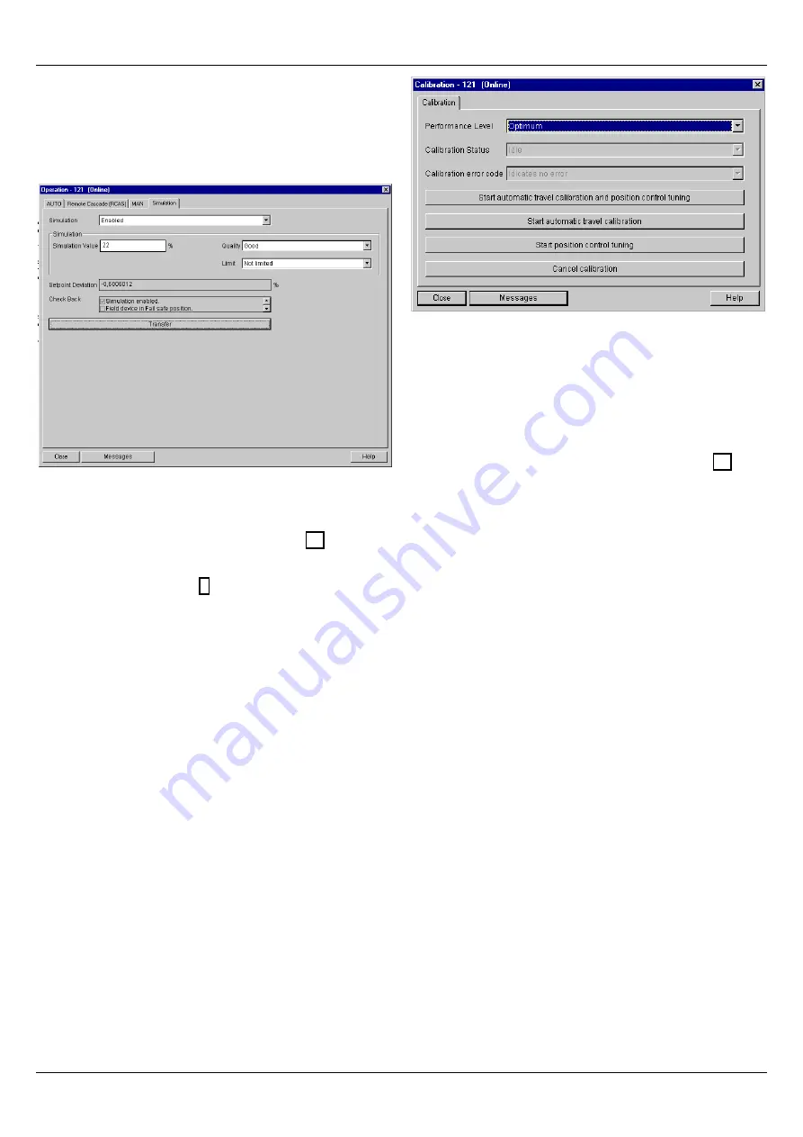
When simulation is enabled, the Analog Output Block and
the Tansducer Block are disconnected. The simulation
value and status are copied to the AO Block Readback
signal. Simulation is useful during the device commission-
ing and maintenance.
Figure 10.
Operation / Simulation.
3.2.2 Calibration
The calibration window is presented is figure 11.
Before starting the calibration, check that the assembly
related parameters (page 8) match with the physical in-
stallation of the device.
The calibration procedure can be started by clicking one of
the three Start buttons. It is possible to run the automatic
travel calibration and the position control tuning either both
at the same time or separately. The calibration can be
stopped any time by clicking the Cancel button.
Once the calibration has been started, the on-line calibra-
tion status is shown in the "Calibration Status" parameter.
If the calibration fails, the reason for the failure is reported
in the parameter "Calibration error code". After the failed
calibration, first check the assembly related parameters. If
the parameters are correct, see ND9000P Installation,
Maintenance and Operating Instructions (IMO) for further
information.
FOR SAFETY'S SAKE
: Calibration moves the valve from a
closed position to a fully open position. Check that you are
allowed to perform calibration, and that it will not endanger
people or processes.
Figure 11. Calibration.
3.2.3 Flow characterization
The Flow modification allows you to modify the flow char-
acteristics curve of the valve to improve controllability of the
valve and optimise control loop performance.
The characterisation window is presented in figure 12.
There are three options for Flow characterization
•
No charaterization
: Charaterization is not used
Charaterization polynom
: Flow Modification is used.
If you select this option, enter a Polynomial Factor
value.
User defined curve
; Flow Modification is used. If you
select this option, enter the user defined curve values
(21 values) in the page User table.
Polynomial Factor describes the nearest approximate or
the exact shape of the valve characterization transfer func-
tion based on the following hyperbolic function:
f(x) = x/(S+x(1-S)),
where
S = Polynomial Factor
x = normalized (0-100%) Setpoint value
f(x) = an intermediate calculation of the Target Position.
If Polynomial Factor is
between 0 and 1
, a quick
opening transfer function is applied.
If Polynomial Factor is
1
, a linear transfer function is
applied.
If Polynomial Factor is
larger than 1
, an equal per-
centage transfer function is applied.


