10
2 L6 70 en
If the reason for the leakage does not become apparent
after doing the above, the valve must be disassembled for
replacing the parts.
5.5
Replacing the seat ring
Ensure that the valve is not pressurized.
Remove the valve from the pipeline. The valve must
be in a closed position during removal.
Follow the lifting methods shown in Section 3.
5.5.1
L6C, L6D, L6F/D and L4F/D
Remove the clamp ring (2) by untightening the
screws (27).
Remove the old body seal (19) and the seat ring (4).
Change the seat ring if it is damaged.
Clean all the surfaces of the seats and check the sur-
face of the seat ring.
Check also the condition of the disc. A damaged disc
must be changed (see Section 5.6).
Check the condition of the pin connection. Repair it
if necessary (see Section 5.6).
Mount a new, self-adhesive body seal (19) into the
body. The surface must be clean and free of grease.
Handle the ends of the seal according to Fig. 15.
Spray a thin layer of dry lubricating fluid, e.g.
Molykote 321R or equivalent, into the seat groove,
surfaces of the clamp ring, seat ring and screws.
Centre the seat ring (4) carefully into its groove and
turn the disc to maintain light contact with the seat.
Mount the clamp ring and tighten the screws (27)
lightly.
Turn the disc slightly open and pull it back to set the
seat into the proper position.
Tighten the screws (27) crosswise and evenly. First to
50 % of recommended torque, then to 100 %.
Recommended torque values for screws are listed in
Table 10. An unevenly tightened flange may damage
the seat ring. The screw heads must be below the
flange surface in lug type valves.
Check the position between the seat ring and the
disc. The valve closes clockwise (see Fig. 14).
Mount the actuator into the valve. Adjust the closed
position limit and check the open position limit (see
Section 6).
5.5.2
L6F
Remove the clamp ring (2) and the old seat ring (4).
Clean up graphite from the body groove.
Polish the contact surface of the new body seal with
emery paper (grade 240). Also polish the edge of the
disc.
Spray a thin layer of dry lubricating fluid, e.g.
Molykote 421R, to the edge of the disc.
Mount a new graphite body seal (19) to the body
and then the seat ring (4).
Mount the clamp ring (2). Tighten the screws (27)
lightly, so that the seat ring (4) is still moveable.
Ensure that the valve is well supported on a stable,
horizontal surface.
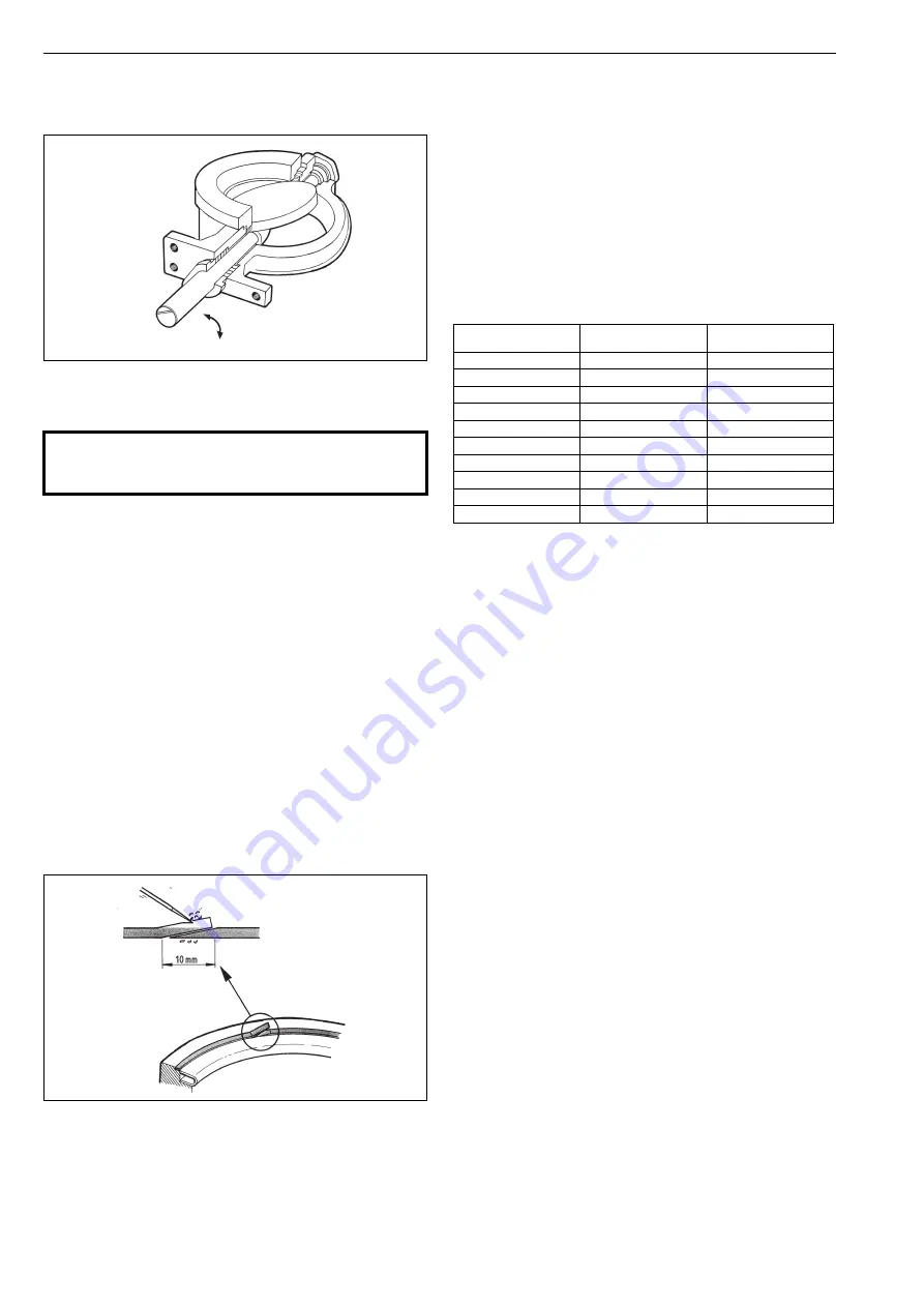
Turn the disc with a suitable lever to the horizontal
(=fully closed) position. Lock the lever to this posi-
tion, e.g. using a lifting crane, to prevent the disc
moving in the open direction. See Fig. 16.
Tighten the screws (27) crosswise, see Table 10 for
recommended torques.
Operate the disc to the open position and check the
contact between the seal and the disc. The trace left
in the disc by the seat should be continuous around
the disc. If not, remount the seat ring.
Fig. 14.
Open and closed positions of the valve
CAUTION:
Do not dismantle the valve or remove it from the pipe-
line while the valve is pressurized!
Fig. 15.
Mounting the body seal
open
closed
Table 10.
Clamp ring/blind flange screw torque, Nm ±10 %
Thread
mm / (UNC)
Clamp ring
Blind flange
M6, 1/4
14
11
M8, 5/16
19
15
M10, 3/8
38
29
M12, 1/2
66
51
M16, 5/8
160
123
M20, 3/4
310
240
M22, 7/8
420
324
M24, 1
540
416
M32, 1 1/4
1430
1100
M38, 1 1/2
2380
1830
Summary of Contents for NELDISC L4 Series
Page 34: ...34 2 L6 70 en ...
Page 35: ...2 L6 70 en 35 ...


