Metso Jamesbury VPVL-051 Installation Maintenance And Operating Instructions Download Page 7

7

B. Apply silicone grease to the end-cap o-ring seals,

using the recommended o-ring-area grease listed
in 

(Table 2)

. Fit the end-cap o-ring seals (14) into

the groove in each end cap (30, 31).

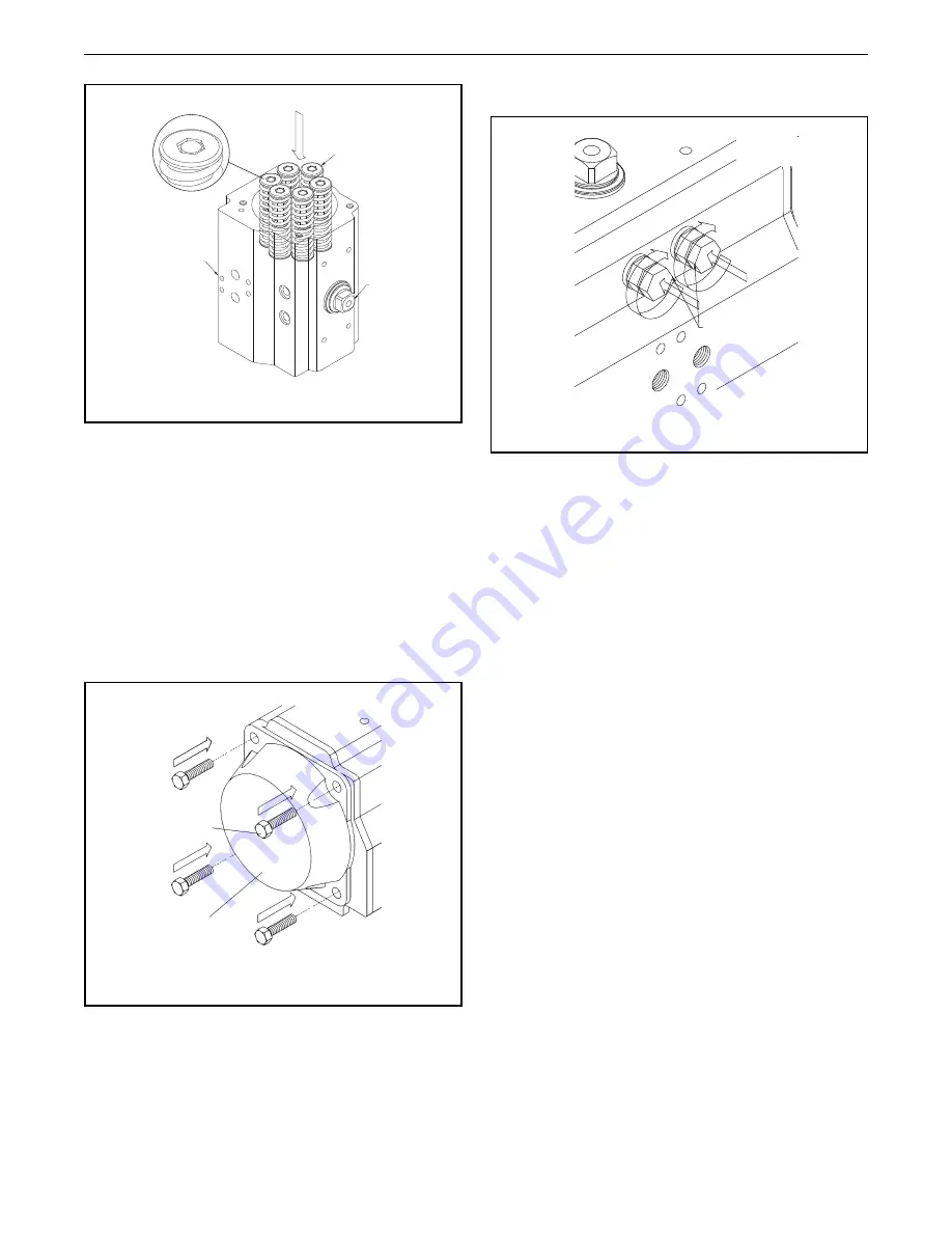
C. Fit the end caps (30, 31) onto the body (50),

verifying that the o-ring seals (14) remain in the
grooves.

D. Insert all end-cap screws (13) and hand tighten.

Complete tightening by following the sequence
indicated in 

(Figure 16)

.

4. Assembly of Stop Screws (2) and Stroke

Adjustment. (Figure 17):

A. Insert the nut (4), washer (3), and o-ring (11) onto

the stop screws (2).

B. Screw the stop screws (2) into the body (50).

5. External Travel Stop Adjustment, (Figure 17):

The stop adjustment screw (2) to the right controls the
clockwise end of travel. The stop adjustment screw (2) to
the left controls the counter-clockwise end of travel.

A. Cycle the actuator/valve to the clockwise end of

travel and measure to determine if the valve is in
the proper position. (In most applications this
will be fully closed.)

B. If the valve is not in the correct clockwise position,

turn the right stop adjustment screw (2) IN to
reduce actuator travel, or OUT to increase actuator
travel.

C. When the correct clockwise position is obtained,

hold the adjusting screw (2) stationary while
tightening the lock nut (4).

D. Cycle the actuator/valve to the counter-clockwise

end of travel and measure to determine if the valve
is in the proper position. (In most applications
this will be fully opened.)

E. If the valve is not in the correct counter-clockwise

position, turn the left stop adjustment screw (2)
IN to reduce actuator travel, or OUT to increase
actuator travel.

F. When the correct counter-clockwise position is

obtained, hold the adjusting screw (2) stationary
while tightening the lock nut (4).

6. Position Indicator (19, 39) Assembly. (Figure 18):

A. Fit position indicator (19) on the shaft (60),

verifying that it indicates the correct actuator
position.

B. Tighten cap screw (39) to secure the position

indicator.

Figure 16

3

13

1

30, 31

4

2

Figure 17

2, 3, 4, 11

Figure 15

60

17

50

Summary of Contents for Jamesbury VPVL-051

Page 1: ...LE OF CONTENTS 1 GENERAL 2 1 1 Warning 2 2 TECHNICAL DATA 2 3 INSTALLATION 3 3 1 General 3 3 2 Operation 3 4 MAINTENANCE 3 4 1 General 3 4 2 Disassembly 3 4 3 Assembly 4 5 SAFETY LOCKOUT DEVICE 9 6 ACTUATOR STORAGE 10 7 REPAIR KITS SPARE PARTS 10 8 EXPLODED VIEW 10 Parts List 11 Read entire instructions carefully before installation or servicing ...

Page 2: ...VE END CAPS WHILETHE ACTUATOR IS PRESSURIZED 4 BEFORE INSTALLING THE VALVE AND ACTUATOR BE SURE THAT THE INDICATOR ON TOP OF THE ACTUATOR CORRECTLY SHOWS THE VALVE POSITION FAILURE TO ASSEMBLE THESE PRODUCTS TO INDICATE THE CORRECT VALVE POSITION COULD RESULT IN PERSONAL INJURY 5 AN ACTUATOR MUST BE SIZED ACCURATELY FOR PROPER OPERATION REFER TO INFORMATION ON ACTUATOR OUTPUT TORQUES IN THIS BULLE...

Page 3: ...nditions the actuator requires only periodic observation to ensure proper adjustment Service kits are available to replace seals and bearings soft parts These parts are identified in Figure 23 and listed in Table 3 Table 1 below lists kit part numbers 4 2 Disassembly Whendisassemblyoftheactuatorisrequiredformaintenance remove the actuator from the valve Ensure proper lifting procedures are followe...

Page 4: ...ect the piston teeth for signs of wear Replace piston if wear seems excessive B Remove piston o ring seal 16 using a screwdriver Remove the piston head 15 and piston back 5 bearings Discard bearings if replacing all soft parts 5 Drive Shaft 60 and Bearing 6 7 Disassembly Figure 7 A Remove spring clip 18 carefully using snap ring pliers Remove external thrust bearing 8 and thrust washer 10 B Apply ...

Page 5: ...octi cam 1 should align with the edges of the square in the bottom of the shaft 60 Insert the internal thrust bearing 8 over the octi cam 1 Fully insert the shaft into the body 50 D Install the external thrust bearing 8 thrust washer 10 and the spring clip 18 2 Piston 40 Assembly Figures 10 through 13 A Install the piston o ring seal 16 and the piston head 15 and piston back 5 bearings B Apply sil...

Page 6: ...17 as shown in Figure 15 6 D Ensure that the octi cam 1 is in the correct position as shown by Figure 11 E For standard rotation assembly clockwise to close rotate the body 50 40 45 counterclockwise if viewingthebottomoftheactuator orclockwise if viewing the top of the actuator as shown in Figure 12 F Press the two pistons 40 simultaneously into the body 50 until the piston racks are engaged and r...

Page 7: ...proper position In most applications this will be fully closed B If the valve is not in the correct clockwise position turn the right stop adjustment screw 2 IN to reduce actuator travel or OUT to increase actuator travel C When the correct clockwise position is obtained hold the adjusting screw 2 stationary while tightening the lock nut 4 D Cycle the actuator valve to the counter clockwise end of...

Page 8: ...nd cap B Open valve using air pressure NOTE Actuator will leak due to removed travel stop C Use the indicator pointer on top of actuator to determine if valve is open to desired position If not repeat steps 1 3 backing off or screwing in stop screw to attain proper open position of valve D Make sure O ring is in proper position in coun tersunk area on end cap and the washer is in place Tighten dow...

Page 9: ...e 4 B Insert on the special longer screw 226 and standard stop cap screws 02 the special nut 228 the washer 03 and the O ring 11 shown in Figure 20 2 Assembly of stop cap screws A Before inserting the special longer screw 226 or the standard screw 02 into the actuator body check what stop position is required If the stop position is fully close 0 or fully open 90 see Figure 21 Note when the stop s...

Page 10: ...p the pad lock key in a safe place 6 ACTUATOR STORAGE If the actuators are not for immediate use the following precautions must be taken for storage A Store in a dry environment B It is recommended that the actuator be stored in its original box C Do not remove the plastic plugs on the air supply ports 7 REPAIR KITS SPARE PARTS For further information on spare parts and service or assistance visit...

Page 11: ...BR 70Shore A 10 1 Thrust Washer Pinion Stainless Steel EN 10088 3 11 2 O ring Stop Cap Screw Seal Nitrile Rubber NBR 70Shore A 12 2 Piston Guide Polyphthalamide GF Amodel AS1145 13 8 12 2 Cap Screw End Cap Stainless Steel ISO 3506 14 2 O ring End Cap Nitrile Rubber NBR 70Shore A 15 2 Bearing Piston Head Polyphthalamide Amodel ET1001HS 16 2 O ring Piston Nitrile Rubber NBR 70Shore A 17 min 4 max 12...

Page 12: ...l int 33 0 3 89 50 64 00 Fax int 33 0 3 89 50 64 40 North America 44 Bowditch Drive P O Box 8044 Shrewsbury Massachusetts 01545 8044 USA Tel int 1 508 852 0200 Fax int 1 508 852 8172 Latin America Av Independência 2500 Iporanga 18087 101 Sorocaba São Paulo Brazil Tel int 55 15 3235 9700 Fax int 55 15 3235 9748 49 Asia Pacific 238A Thomson Road 25 09 Novena Square Tower A 307684 Singapore Tel int 6...

Reviews: