


IMO-227 EN
7
IMO 8/17
5. If the valve has the “leak-off” option, remove any
remaining “leak-off” port fittings or plugs.
6. The insert design requires that the insert (2) be
unthreaded in a counter clockwise motion using the
following method utilizing the insert field wrench.
Assemble the field wrench as follows (see Figures 5
and 19):
a. Place the driver (A) into the insert (2) slots.
b. Put the plate (C) on top of the driver (A).
c. Place the studs (E) through the plate (C) and flange
holes. Thread the nuts (F) onto the stud below the
flange.
d. On the top side of the plate (C) put a flat washer (G),
die spring (H), flat washer (G), and nut (F). Tighten to
slightly compress spring
7. Place a pipe or rod through the driver (A) and loosen
the insert (2) by turning counterclockwise.
8. Remove the tool and lift out the insert (2).
9. Place the valve in the vertical position with the insert
end up.
10. Rotate the stem so that the ball is in the closed position
for removal. If the ball (3) does not swing free from the
body, with the ball in the fully closed position, use a
piece of wood or some other soft material to gently
tap the ball (from the end opposite the body cap). This
should loosen the ball so that it can be pivoted free of
the steam (4). Lift out the body seal (6), seat (5), and the
ball (3). The bottom grounding spring (71), located in
bottom of the steam (4), may fall out at this time. If the
spring does not fall out with the stem, remove it from
the stem to prevent it from being lost.
11. Carefully remove the bottom seat (5) out of the body,
BEING CAREFUL NOT TO SCRATCH THE BODY
SEALING SURFACE BEHIND THE SEAT.
12. Remove the retaining ring (72) and grounding spring
(70) from stem (4).
13. Remove hex nuts (30), disc springs (31) and compres-
sion plate (20). Pay careful attention to the orientation
of the disc springs (31) and make sure they are in the
same orientation during assembly.
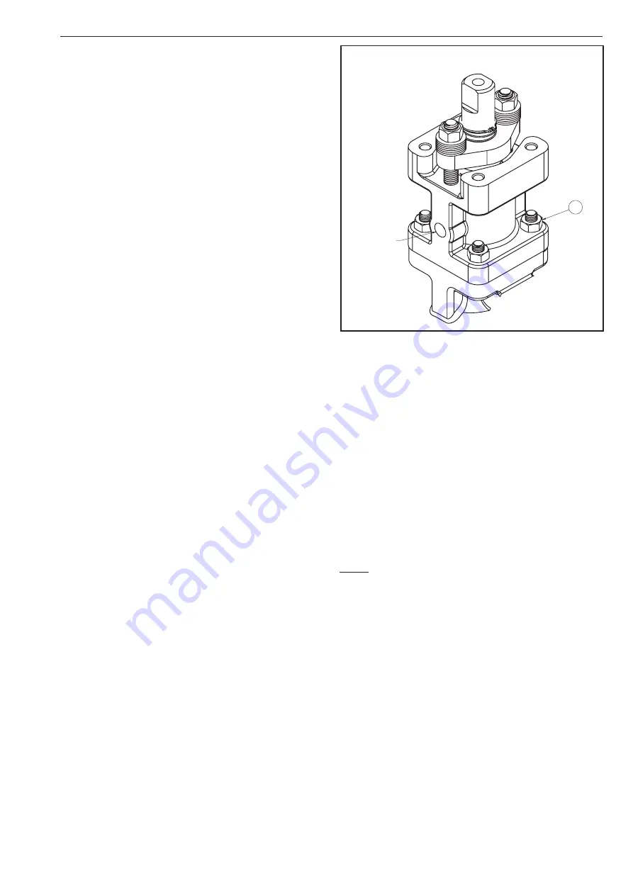
14. Remove hex nuts (111) and lift the
Emission-Pak
hous-
ing (101) straight up until the ball end of the stem
clears the valve body (1) (see Figure 6 and 20).
15. Carefully remove and discard the inner and outer stem
retainer seals (105) and (106).
16. From the
Emission-Pak
housing (101) remove the
stem (4), stem bearings (13), secondary stem seal
(7), stem seals (104), bearing strip (109) and lantern
ring (103), BEING CAREFUL NOT TO DAMAGE ANY
SEALING SURFACE.
Figure 6
4 .6
Checking Parts
1. Clean all disassembled parts.
2. Check the stem (4) and ball (3) for damage. Pay partic-
ular attention to the sealing areas.
3. Check all sealing and gasket surfaces of the body (1)
and insert (2).
4. Replace any damaged parts.
5. Replace any fastener where the threads are damaged
or have been heated, stretched or corroded.
6. Replace any parts that have cracks, gouges or pits that
will affect sealing.
NOTE: When ordering spare parts, always include the fol-
lowing information:
a. Valve catalog code from Identification plate,
b. If the valve is serialized – the serial number (stamped
on the valve body or indentification plate).
c.
From Figure 19 or 20, the ballooned part number, part
name and quantity required.
4 .7
Assembly – Bare Stem Valves
It is advisable to replace seats and seals if complete dis-
assembly and reassembly become necessary. Refer to the
Repair Kit chart (see Table 9A). A lubricant, compatible with
the flow media, MUST be applied to the threads on insert
(2) to prevent galling during assembly.
1. Clean all valve components if not done previously.
111
OPTIONAL
LEAK-OFF PORT
Buy: www.ValinOnline.com | Phone 844-385-3099 | Email: [email protected]