background image

9

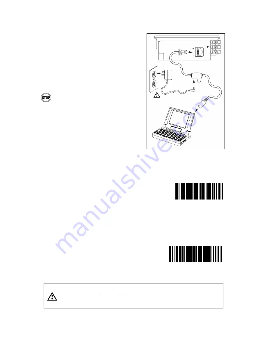
Figure 15:

Stand-Alone
Keyboard Interface

I

NSTALLATION FOR 

S

TAND

-A

LONE 

K

EYBOARD 

I

NTERFACE

1.  Turn off the host system.

2.  Disconnect the keyboard from the host.

3.  Connect the PowerLink cable to the 2

nd

jack from the top of the MS7600.

4.  Connect the other end of the PowerLink

cable to the keyboard port on the host.

Before continuing verify that the
PowerLink cable is connected to the
appropriate interface jack on the
scanner.  An incorrect cable connection
can cause communication problems or
potential damage to the scanner.

5.  Connect the external power supply

to the power jack on the PowerLink
cable.

6.  Check the AC input requirements

of the power supply to make sure
the voltage matches the AC outlet.

7.  Connect AC power to the transformer.

The outlet should be near the equipment
and easily accessible.

8. Scan 

the 

Load Keyboard Wedge

Defaults

 bar code then the

Enable Stand Alone Keyboard

 bar code

to configure the MS7600 for Stand-Alone
Keyboard communication.

Note:  When scanning the bar codes,

cover the code not being scanned
to ensure the codes are read in
the proper sequence.

9.  Turn on the host system.

Caution:

To maintain compliance with applicable standards, all circuits connected to the scanner must meet the
requirements for SELV (Safety Extra Low Voltage) according to EN 60950.

To maintain compliance with standard CSA C22.2 No. 60950-00/UL 60950 and norm EN 60950, the power
source should meet applicable performance requirements for a limited power source.

³

9

9

9

9

9

4

Scan 1

St

Load Keyboard

Wedge Defaults

³

5 1 5

5 1 5

3

Scan 2

nd

Enable Stand-Alone

Keyboard

Summary of Contents for MS7620

Page 1: ...METROLOGIC INSTRUMENTS INC MS7600 Horizon Series Installation and User s Guide...

Page 2: ......

Page 3: ...e 14 For OCIA Interface 15 Of a Secondary Scanner 16 Scanner Parts 19 Maintenance 20 EAS Deactivation Antenna 20 Scanner Labels 21 Audible Indicators 22 Visual Indicators 23 Failure Modes 24 Changing...

Page 4: ...a high impact plastic MS7620 top plate Firmware updates via Flash ROM Field replaceable window EAS deactivation antenna is standard Supports commonly used interfaces including USB and Keyboard Wedge...

Page 5: ...on to the host Contact a customer service representative for additional information 54 54002 Keyboard Wedge PowerLink Cable with Adapter Cable MVC Metrologic Voltage Converter Cable 12VDC to 5 2VDC or...

Page 6: ...e window type the scanner must be returned to the manufacturer for additional configuration 46 46602 Stainless Steel Top with Sapphire Window 46 46603 Stainless Steel Top with Everscan Window 46 46604...

Page 7: ...ight up to remove There is no hardware required to remove or replace the top cover See caution on page 3 There are two installation tabs under the top cover that can be used to place the unit into the...

Page 8: ...e trim ring MLPN 46 46641 is an optional purchase Contact a Metrologic customer service representative for details at 1 800 ID METRO Before starting to mount the MS7600 determine the direction of pack...

Page 9: ...6 MOUNTING THE MS7600 SERIES OPTION B Free Hanging Support Figure 8 Package Flow right Figure 9 Specifications for free hanging support Figure 10 Installation Tabs...

Page 10: ...7 MOUNTING THE MS7600 SERIES OPTION C Trim Ring MLPN 46 46641 Additional Purchase Figure 11 Counter Top Opening for Trim Ring MLPN 46 46641 Figure 12 Trim Ring MLPN 46 46641 Installation...

Page 11: ...canner 5 Connect the external power supply to the power jack on the PowerLink cable 6 Check the AC input requirements of the power supply to make sure the voltage matches the AC outlet 7 Connect AC po...

Page 12: ...atches the AC outlet 7 Connect AC power to the transformer The outlet should be near the equipment and easily accessible 8 Scan the Load Keyboard Wedge Defaults bar code then the Enable Stand Alone Ke...

Page 13: ...wn from the top of the MS7600 5 Connect the other end of the USB cable to the host Before continuing verify that the USB PowerLink cable is connected to the appropriate interface jack on the scanner A...

Page 14: ...ot guarantee that scanned information will appear at the PC A software driver and correct configuration setting are also required for proper communication to occur 6 Scan the Enable USB Defaults bar c...

Page 15: ...ack on the Power Link Cable 5 Check the AC input requirements of the power supply to make sure the voltage matches the AC outlet 6 Connect AC power to the transformer The outlet should be near the equ...

Page 16: ...TERFACES Step 7 page 12 continued For RS232 Communication Scan 1 st 9 9 9 9 9 8 Recall Defaults Scan 2 nd 4 1 5 5 5 4 Enable RS 232 For Light Pen Communication Scan 1 st 9 9 9 9 9 8 Recall Defaults Sc...

Page 17: ...appear at the PC A software driver and correct configuration setting are also required for proper communication to occur 4 Turn on the host system 5 Scan the Load 46xx IBM Defaults bar code to configu...

Page 18: ...appear at the PC A software driver and correct configuration setting are also required for proper communication to occur 4 Turn on the host system 5 Scan the Load OCIA Defaults bar code to configure...

Page 19: ...erLink cables are connected to the appropriate interface jacks on the scanner An incorrect cable connection can cause communication problems or potential damage to the scanner 7 Insert the attached ru...

Page 20: ...scanner is not a Metrologic scanner refer to Section O of the MetroSelect Configuration Guide 4 3 7 3 3 0 Enable Aux Port The auxiliary input port s data format must match the main output format of t...

Page 21: ...18 INSTALLATION OF A SECONDARY SCANNER Figure 20 Connector Orientation Top Secondary Scanner Setup Bottom...

Page 22: ...perture o Amber LED Located Under Window p Red LED Located Under Window q Speaker r Cable Connection Area s Stainless Steel Top MS7625 units only t Package Flow Indicator Arrow Head u Rubber Connector...

Page 23: ...1 and SW2 are the switch banks inside the Checkpoint Device that set the deactivation range Metrologic recommends end users program the MS7600 to the Fixed Low Density depth of field so that the unit...

Page 24: ...m of the unit The label contains information such as the model number date of manufacture serial number and caution information An additional caution label is located under the top plate The following...

Page 25: ...not beep once and the red light does not flash then the bar code has not been successfully read Razzberry Tone This is a failure indicator Refer to failure modes page 24 Three Beeps during operation W...

Page 26: ...e scanner will beep once If the red LED does not flash or the scanner does not beep once then the bar code has not been successfully read Steady Amber and Steady Red After a successful scan the scanne...

Page 27: ...d a motor failure Return the unit for repair at an authorized service center Continuous Razzberry Tone with both LEDs off If upon power up the scanner emits a continuous razzberry tone then the scanne...

Page 28: ...5 Next Beep Tone Changing the Beeper Volume Volume levels may be programmed directly or incrementally using the following bar code The new volume will be heard followed by a short pause Two more tones...

Page 29: ...non use Any movement detected by the IR will wake the scanner from the power save mode see figure 27 This mode s wake time is slightly longer due to the motor s need to restart 4 Dual Action Power Sa...

Page 30: ...27 POWER SAVE MODES AND IR DETECTION Figure 27 IR Activation Area Parallel to Package Flow Specifications are subject to change without notice...

Page 31: ...SCAN VOLUME SPECIFICATIONS BASED ON 100 UPC BAR CODES Figure 28 Scan Volume in Plane Perpendicular to Flow Figure 29 Scan Volume in Plane Parallel to Flow Specifications subject to change without noti...

Page 32: ...BAR CODE ELEMENT WIDTH BASED ON 100 UPC BAR CODES Figure 30 Depth of Field Perpendicular to Flow Minimum Bar Code Element Width A B C D E mm 13 19 26 33 48 mils 5 2 7 5 10 4 13 19 Specifications subj...

Page 33: ...eries scanner Use the power supply included with the scanner 3 beeps on power up Non volatile RAM failure Contact a Metrologic Representative if the unit will not hold the programmed configuration Con...

Page 34: ...st scan red LED stays on The scanner is configured to support some form of host handshaking but is not receiving the signal If the scanner is setup to support ACK NAK RTS CTS XON XOFF or D E verify th...

Page 35: ...bar code but there is no data Configuration is not correct Make sure the scanner is configured for the appropriate mode The unit scans but the data is not correct Configuration is not correct Make su...

Page 36: ...to detect whether the PC is operating in Caps Lock Everything works except for a couple of characters These characters may not be supported by that country s key look up table Try operating the scanne...

Page 37: ...7600 must be programmed to enable the Aux port Secondary Scanner powers up but data is not relayed to the host The Aux com port may not be operating properly The auxiliary input port s data format mus...

Page 38: ...r other symbologies call Metrologic System Interfaces PC Keyboard Wedge RS 232 OCIA Light Pen Stand Alone PC Keyboard USB IBM 46xx Print Contrast 35 minimum reflectance difference No Characters Read u...

Page 39: ...rs Class II 5 2 V 650 mA Laser Class IEC 60825 1 1993 A1 1997 A2 2001 Class 1 EMC FCC ICES 003 EN 55022 Class B ENVIRONMENTAL Operating Temperature 0 C to 40 C 32 F to 104 F Storage Temperature 40 C t...

Page 40: ...ware and the scanner configuration match If the application does not support RS 232 scanners a software wedge program that will take RS 232 data and place it into a keyboard buffer may be needed This...

Page 41: ...y RS 232 programmable functions available in other Metrologic scanners are also available as keyboard wedge functions The following are the most important selectable options specific to the keyboard w...

Page 42: ...232 LIGHT PEN IBM 46XX KBW USB UPC EAN 9 9 9 9 9 9 Code 128 9 9 9 9 9 9 Code 93 9 9 9 9 9 9 Codabar 9 9 9 9 9 9 Interleaved 2 of 5 ITF 9 9 9 9 9 9 MOD 10 Check on ITF 9 9 9 9 9 9 Code 11 9 9 9 9 9 9...

Page 43: ...9 9 9 9 9 No Beeps on Timeout 9 9 9 9 9 9 Enter Power Save Mode 10 mins 9 9 9 9 9 9 Blink Power Save Mode 9 9 9 9 9 9 Laser OFF Power Save Mode 9 9 9 9 9 9 Laser Motor OFF Power Save Mode 9 9 9 9 9 9...

Page 44: ...ro on UPC E 9 9 9 9 9 9 Convert EAN 8 to EAN 13 a a a a a Transmit UPC A Number System 9 9 9 9 9 9 Transmit UPC A Manufacturer ID 9 9 9 9 9 9 Transmit UPC A Item ID 9 9 9 9 9 9 Transmit Codabar Start...

Page 45: ...ble Command 9 9 DTR Handshaking Support 9 RTS CTS Handshaking 9 Character RTS CTS 9 Message RTS CTS 9 XON XOFF Handshaking 9 ACK NAK 9 Two Digit Supplements 9 9 as code 39 9 9 9 Five Digit Supplements...

Page 46: ...haracters 9 9 9 Prefixes for individual Code Types 9 9 9 Editing 9 9 9 9 9 9 Inter Scan Code Delay Programmable 100 sec steps 800 sec 9 9 Function Control Key Support 9 9 Minimum Element Width Program...

Page 47: ...T PEN IBM 46XX KBW USB Aux Baud Rate 38400 9 9 9 9 9 9 Aux parity space 9 9 9 9 9 9 Aux data bits 7 9 9 9 9 9 9 Aux stop bits 2 9 9 9 9 9 9 Aux character RTS 9 9 9 9 9 9 Aux message RTS 9 9 9 9 9 9 Au...

Page 48: ...13 OCIA MS762x 13 IBM 46xx Pin Function Pin Function 1 Ground 1 Ground 2 NC 2 RS 232 Transmit Output 3 NC 3 RS 232 Receive Input 4 RDATA 4 RTS Output 5 RDATA Return 5 CTS Input 6 Clock in 6 DTR 7 Cloc...

Page 49: ...or USB MS762x 37 RS 232 or Light Pen Pin Function Pin Function 1 Ground 1 Ground 2 USB D 2 RS 232 Transmit Output 3 USB D 3 RS 232 Receive Input 4 PC Data 4 RTS Output 5 PC Clock 5 CTS Input 6 KB Clo...

Page 50: ...to the host USB PowerLink Cable MLPN 54 54165 Type A Pin Function 1 N C 2 D 3 D 4 Ground PowerLink RS232 LSO AUX Cable MLPN 54 54667 Pin Function 1 Ground 2 RS 232 Transmit Output 3 RS 232 Receive In...

Page 51: ...ing to the keyboard and the keyboard port on the PC The pin assignments are as follows PowerLink Cable Adapter Cable 5 pin Female DIN 5 pin Male DIN Pin Function Pin Function 1 Keyboard Clock 1 PC Clo...

Page 52: ...dealer reseller or retail consumer or refund an amount equal to the original purchase price This limited warranty does not extend to any Product which in the sole judgement of Metrologic has been subj...

Page 53: ...quipment into an outlet on a circuit different from that to which the receiver is connected Consult the dealer or an experienced radio TV technician for help Notice This Class B digital apparatus comp...

Page 54: ...versuchen den Laser Scanner selbst zu warten Sehen Sie niemals in den Laserstrahl selbst wenn Sie glauben da der Scanner nicht aktiv ist ffnen Sie niemals den Scanner um in das Ger t hineinzusehen We...

Page 55: ...4 924 5 340 973 5 396 053 5 396 055 5 408 081 5 410 139 5 424 525 5 436 440 5 449 891 5 468 949 5 468 951 5 479 000 5 484 992 5 525 789 5 528 024 5 532 469 5 545 889 5 591 953 5 616 908 5 627 359 No l...

Page 56: ...Installation 8 10 12 18 Interfaces 9 10 12 15 30 IR Detection 26 K Keyboard Type 38 Keyboard Wedge 1 2 8 35 38 46 L Labels 21 LED 19 22 23 30 31 35 Light Levels 36 Light Pen 1 12 14 35 38 44 46 Light...

Page 57: ...54 INDEX T Termination 35 Transformers 36 Troubleshooting 30 31 32 33 34 U USB 10 V Ventilation 36 Visual 23 Voltage 8 16 W Warranty 49 Weight 35...

Page 58: ......

Page 59: ...August 2002 Printed in the USA 0 0 0 2 8 7 0 B...

Reviews: