background image

39

Parameter

Default

OCIA

IBM

RS-

Parallel

Light Pen

46XX

232*

Transmit UPC-

*

T

T

T

T

A Number
System

Transmit

T

T

T

T

Codabar
Start/Stop
Characters

CLSI Editing

T

T

T

(Enable)

Transmit Mod

T

T

T

43 Check Digit
on Code 39

Transmit Code

T

T

T

39 Stop/Start
Characters

Transmit Mod

T

T

T

10/ITF

Transmit Code

T

T

T

T

11 Check Digit

Transmit MSI-

T

T

T

Plessey Check
Characters

Parity

Space

T

Baud Rate

9600

T

8 Data Bits

T

7 Data Bits

*

T

Transmit Sanyo

T

ID Characters

Nixdorf ID

T

Shell

T

Schulmberger
Formatting

UPC Prefix

T

UPC Suffix

T

Transmit AIM

T

ID Characters

Summary of Contents for MS700i

Page 1: ...MS700i Series Laser Bar Code Projection Scanner Installation and User s Guide MLPN 2178 Printed in USA October 1998...

Page 2: ...tore Controller Running 4680 OS or 4690 OS 8 IBM 4684 and 4694 Systems 8 Scanner Installation to a PC Keyboard Port 9 10 PC Application Note 11 Installation of the MS700 Series Stand 12 Attaching the...

Page 3: ...r the MS700i and MS715i 28 29 Depth of Field for the MS720i Scanner 30 Depth of Field and Symbol Specification for the MS720i 31 32 Maintenance 33 Applications and Protocols 33 Appendix A Specificatio...

Page 4: ...from the top or front and a volume control card that can be scanned to control volume levels There are two programming methods through the ScanSelect programming guide or through ScanSet an IBM PC com...

Page 5: ...Guide MLPN 2178 ScanSelect Scanner Programming Guide MLPN 2186 Volume Control Card MLPN 2346 MS700i MS715i or MS720i Laser Bar Code Projection Scanner Power Supply optional Communication cable with c...

Page 6: ...eceive power from a transformer skip to Step 5 3 If the scanner will receive power from an external power source check the AC input requirements of the transformer to make sure the voltage matches the...

Page 7: ...anSelect Scanner Programming Guide When using ScanSet refer to the ScanSet documentation for information on how to configure the scanner 1 Connect the scanner to the host system Refer to the Scanner C...

Page 8: ...the cloning cable MLPN 51544 between two scanners 1 Turn off both scanners 2 Connect the cloning cable between the two scanners 3 Turn both scanners on by plugging in the transformers 4 Once each sca...

Page 9: ...connection all devices use a common communications bus inside the 46XX terminal Each device uses a different address when it must communicate The terminal must be configured to look for a device at a...

Page 10: ...ffer within two seconds it is discarded without giving the operator a good scan indication This accommodates newer versions of the IBM device drivers that enable disable scanning in many different sit...

Page 11: ...the scanner Regarding the 4690 OS at the time of this printing Metrologic does not know exactly which terminal port configuration screen is used for selecting scanners It should be listed under the Po...

Page 12: ...th one 1 5 Pos female DIN connector and one 1 6 Pos male mini DIN connector The kit also includes an adaptor cable This cable allows the scanner to plug into an IBM PC XT or AT compatible computer or...

Page 13: ...the PC off 3 Disconnect the keyboard from the PC 4 Plug the communication cable to the PC and the keyboard Refer to Figure 1 5 Connect the 25 pin D type connector on the scanner s head cable to the co...

Page 14: ...r scan code options Note Once the scanner connects to the PC the PC can be turned on and will operate normally even if the scanner s transformer plug is not in How ever bar codes will not be read unti...

Page 15: ...Base 6 Internal Lock Washer 7 Flexible Shaft 1 Use the 2 inch x 2 inch stand base to mark the position for pilot holes 2 Use the four wood screws to secure the base to the work surface 3 Position the...

Page 16: ...iding the scanner into place loosen the small screw A located in the center of the long part of the shoe with a 3 32 hex key wrench Refer to Figure 3 2 Align the foot of the scanner with the shoe of t...

Page 17: ...on the scanner has read a bar code successfully When the red light turns off communication to the host is complete 3 InfraRed Object When a specified time has elapsed Sensor without any scanning the...

Page 18: ...o on This occurs when an object is in the scan field The green LED will remain on until the IR time out has elapsed or until the scanner is turned off Steady Green Red Flash When the scanner successfu...

Page 19: ...le palpeur La diode verte reste allum e tant que la temporisation de l infrarouge dure ou jusqu ce que le scanner soit d sactiv La diode verte reste allum e la diode rouge clignote Apr s lecture avec...

Page 20: ...ch ein Objekt im Abtastfeld befindet Die gr ne Leuchtdiodenanzeige leuchtet solange auf bis das Infrarot Timeout abgelaufen ist oder bis der Scanner abgeschaltet wird Feststehende gr ne Leuchtanzeige...

Page 21: ...odo luminoso verde acceso fino al r aggiungimento del timeout infrarossi oppure fino allo spegnimento dello scanner Il diodo luminoso verde acceso quello rosso lampeggia Dopo la lettura riuscita di un...

Page 22: ...the volume of the scanner by scanning the bar codes on the volume control card To permanently change the volume of the scanner enter program mode and scan the appropriate volume setting bar code in Se...

Page 23: ...the device is a CDRH Class IIa laser product and IEC 825 LASERKLASSE 1 Also on each scanner is a label located on the back of the unit This label contains information such as the model number date of...

Page 24: ...computer is on standby passing an object in front of this sensor device will wake up the scanner and activate the laser The scanner will enter standby when it remains dormant for a time When the gree...

Page 25: ...22 Symbol Orientation To scan a symbol it may be oriented in any of the degree angles shown in Figure 5 The roll pitch and yaw are 360E 60E and 60E respectively Figure 5...

Page 26: ...wn in the section Symbol Orientation page 22 Planes formed by each of the five scan segments define the bottom of the region The 178mm 7 0 depth of field of each of the scan segments bound the top Bes...

Page 27: ...of the region is 7 from the scanner window Planes formed by each of the five scan segments define the sides The 203mm 8 0 depth of field of each of the scan segments bound the top Best first pass rea...

Page 28: ...25 Horizontal Scan Width vs Distance for the MS700i and MS715i Scanner The following illustration notes the measurements of the horizontal scan width at given distances Figure 8...

Page 29: ...26 Horizontal Scan Width vs Distance for the MS720i Scanner The following illustration notes the measurements of the horizontal scan width at given distances Figure 9...

Page 30: ...each scan segment This 0 0mm 178mm 0 7 range is the depth of field for the MS700i and MS715i scanner refer to Figure 10 This area of active scanning projects out from the glass on the face of the scan...

Page 31: ...ent Mil 1 1000 UPC EAN 10 4 80 0 5 UPC EAN 13 0 100 0 7 Code 39 7 5 High 0 4 Code 39 12 0 Medium 1 7 Code 39 21 0 Low 3 11 I 2 of 5 7 5 High 0 4 I 2 of 5 12 0 Medium 1 7 I 2 of 5 21 0 Low 3 11 Codabar...

Page 32: ...29 Figure 11...

Page 33: ...15 0 measured along the scanning beam at the center of each scan segment This 178mm 381mm 7 15 range is the depth of field for the MS720i scanner Refer to Figure 12 The scan pattern is projected at a...

Page 34: ...ty Depth of Field Element Mil 1 1000 UPC EAN 10 4 80 7 11 UPC EAN 13 0 100 7 15 Code 39 12 0 Medium 7 15 Code 39 21 0 Low 9 17 I 2 of 5 12 0 Medium 7 15 I 2 of 5 21 0 Low 9 17 Codabar 12 0 Medium 7 15...

Page 35: ...32 Figure 13...

Page 36: ...es the scanner number and communications protocol Scanner Version Identifier Communication Protocol s 700i 715i 720i 1 and 21 RS 232 OCIA Light Pen Emulation 700i 715i 720i 2 Parallel Output OCR A B 7...

Page 37: ...lass A Mechanical Dimensions 165mm x 165mm x 76mm 6 5 L x 6 5 W x 3 0 D Footprint on Stand 64mm x 64mm 2 5 x 2 5 Weight 1 13kg 2 5 lbs Orientation May be used in any orientation Mounting Fully adjusta...

Page 38: ...eriodically Decode Capability Auto discriminates System Interfaces RS 232C OCIA Parallel IBM 468X 469X Light Pen Emulation Point to Point RS 422 PC Keyboard Wedge Print Contrast 35 minimum reflectance...

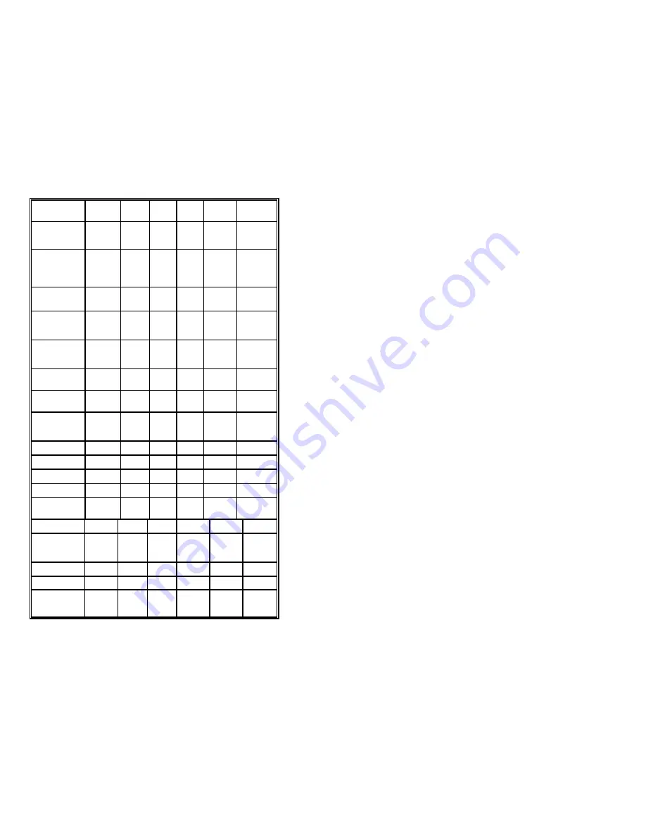
Page 39: ...es not support every parameter If the communication supports a parameter listed in the charts on the following pages a check mark will appear Parameter Default OCIA IBM RS Parallel Light Pen 46XX 232...

Page 40: ...gh as T Code 39 Spaces High as T Code 39 Bars High as T Scanned Spaces High as T Scanned DTS SIEMENS T DTS NIXDORF T NCR F T NCR S T Poll Light Pen T Source Beeper Tone Normal T T T T T Volume Setting...

Page 41: ...ymbol T T T T T Rescan Timeout 500 msecs Same Symbol T T T T T Rescan Timeout 1250 msecs Same Symbol T T T T T Rescan Timeout 2000 msecs Scanability Off T Intercharacter 1 msecs T T T Delay Scan Buffe...

Page 42: ...Mod T T T 43 Check Digit on Code 39 Transmit Code T T T 39 Stop Start Characters Transmit Mod T T T 10 ITF Transmit Code T T T T 11 Check Digit Transmit MSI T T T Plessey Check Characters Parity Spac...

Page 43: ...32 Pen STX Prefix T ETX Suffix T Carriage Return T Line Feed T Tab Prefix T Tab Suffix T DE Disable T Command FL Laser T Enable Command DTR T Handshaking Support RTS CTS T Handshaking Character T RTS...

Page 44: ...ollowing Two Digit T T T T Supplements Five Digit T T T T Supplements Bookland T T T T 977 2 digit T T T T Supplemental Requirement Supplements are T T T T not Required Two Digit T T T T Redundancy Fi...

Page 45: ...same time scanner is purchased The version 1 and 21 scanners are designed to be used for RS 232 OCIA or Light Pen Emulation communication The following is a list of the pin assignments The pin number...

Page 46: ...time scanner is purchased The version 2 scanner is designed to be used for Parallel communication The following is a list of the pin assignments The pin numbers are impressed on the head cable s conne...

Page 47: ...scanner is designed to be used for Point to Point RS 422 communication The following is a list of the pin assignments The pin numbers are impressed on the head cable s connector Pin Function 1 AC Shie...

Page 48: ...are designed to be used primarily with IBM 46XX series of electronic cash registers It can also be configured to communicate using the full RS 232 and OCIA protocol The following is a list of the pin...

Page 49: ...emulation interface When configuring the scanner for one interface versus another change all necessary parameters for that particular interface For instance to configure the scanner for keyboard wedge...

Page 50: ...le judge ment of Metrologic has been subjected to misuse neglect improper installation or accident nor does it extend to any Product which has been repaired or altered by anyone who is not a Metrologi...

Page 51: ...nd haften nicht f r die Richtigkeit im Hinblick auf Inhalt oder Genauigkeit der Angaben dieser Ver ffentlichung oder des hierin beschriebenen Produkts Sie bernehmen ebenso keinerlei Eignungsgarantie o...

Page 52: ...ard Remarque Apr s contr le de cet appareil on a not qu il r pondait aux valeurs limites de la classe A c onform ment la partie 15 des directives de l administration f d rale am ricaine pour les t l c...

Page 53: ...en Der Einsatz optischer Ger te mit dieser Laserausr stung erh ht das Risiko einer Sehsch digung N B Dal controllo di questo apparecchio risulta che esso risponde ai valori limite per apparecchi digit...

Page 54: ...24 924 5 396 053 5 396 055 5 408 081 5 410 139 5 436 440 5 449 891 5 468 949 5 479 000 5 532 469 5 545 889 No license right or sublicense is granted either expressly or by implication estoppel or othe...

Page 55: ...s buffer 7 Communications bus 6 Compliance 3 10 Configuration 4 6 8 9 46 Contrast 35 Copyright ii Current 34 Customer Service ii 47 D DC transformer 34 Decode capability 35 Default settings 36 41 Dept...

Page 56: ...window 14 33 P Parts 14 Patents 51 PC 1 9 10 11 35 46 Pin assignments 42 46 Port s 6 9 Print contrast 35 Programming guide 1 2 4 9 19 21 46 Protocols 33 R Red LED 14 15 Repair 47 Rights property 51 w...

Page 57: ...56 U UL CSA TUV 34 USA corporate headquarters ii V Ventilation 35 Version identifiers 33 Voltage 3 10 34 Volume control card 52 53 W Warranty 47 Watt s 1 34 Weight 34 Window 1 24 27 30 33 35...

Reviews: