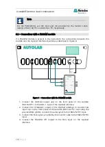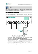
Autolab/Electronic load combination
22 |
P a g e
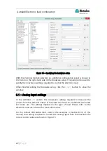
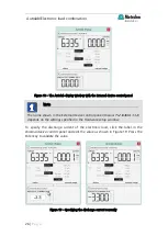
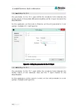
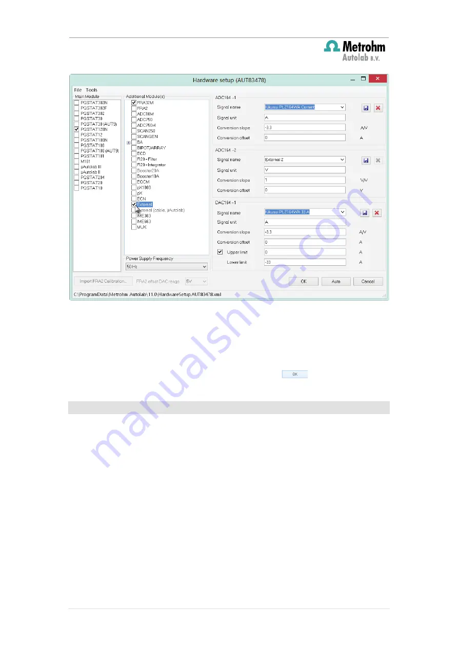
Figure 14 – Specifying the hardware setup
With the
External module selected, an additional configuration panel is shown in
the frame on the right-hand side of the Hardware setup. This panel can be used to
specify the conversion settings required to control the electronic load.
When finished editing the Hardware setup, click the
button to close the
window.
9.1
– Analog input settings
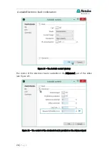
In the ADC164 – 1 section, the conversion settings required to measure the
current from the external output of the electronic load can be defined and saved
for future use. The settings depend on the type of load. Please refer to the
electronic load user manual for more information.
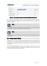
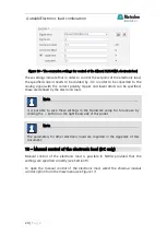
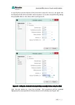
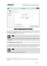
For the Kikusui PLZ164WA load, used in the examples in Section 8.3.2 of this
manual, the settings required to convert the analog signal from the load into the
correct current value are shown in Figure 15.

