background image

8

  Installation Guide

Connect to the Network

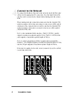
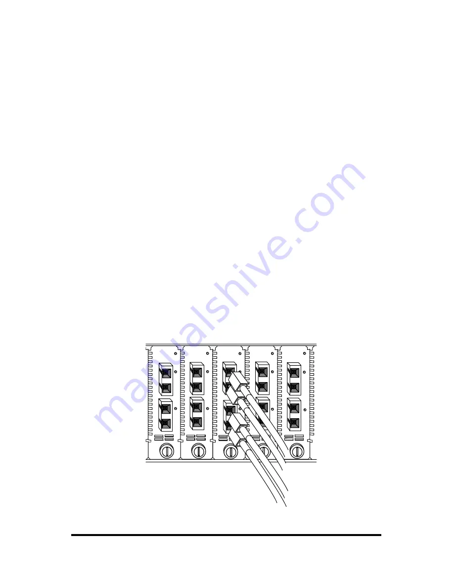
To connect the Radiance line card to the network, insert the fiber optic
cables into the appropriate SC connectors. (See the figure below.) Be
sure the card is secured to the chassis before making network connec-
tions.

When making network connections, make sure that the transmit (TX)
optical conductor of the line card connects to the receive (RX) optical
conductor of the connected device; and be sure that the transmit (TX)
optical conductor of the device connects to the receive (RX) optical
conductor of the card.

Port 1 is the multimode (MM) interface. The OC-3/STM-1 models
support a maximum segment length of 2 km. The OC-12/STM-4 line
card supports a maximum segment length of 500 m.

Port 2 is either a singlemode (SM) or singlemode long haul (LH)
interface.  The SM port supports a maximum segment length of 15 km,
and the LH port supports a maximum segment length of 40 km.

Once power is applied to the unit, correct connectivity can be verified
via the link (LK) LED.

PWR

M
M

OC-12

R
X

LK

LK

T
X

S

M

R
X

T
X

LX

LK

LK

PWR

OC-3

S

M

M
M

PWR

OC-3

LK

LK

M
M

L
H

R
X

T
X

LK

PWR

M
M

OC-12

R
X

LK

S

M

T
X

PWR

LK

L
H

M
M

OC-3

R
X

T
X

R
X

T
X

R
X

T
X

R
X

T
X

LK

R
X

T
X

R
X

T
X

4

Summary of Contents for Radiance Sonet Single Interface Line Cards R125-34

Page 1: ...tion User Guide Models R125 34 R125 37 R135 34 RADIANCE SONET SINGLE INTERFACE LINE CARDS PWR OC 3 M M L H R X LK LK R X T X T X PWR M M OC 12 S M R X LK LK R X T X T X PWR OC 3 M M S M R X LK LK R X...

Page 2: ...ctric electronic electromagnetic mechanical chemical optical or otherwise without prior explicit written permission of Metrobility Optical Systems Inc 2001 02 2004 Metrobility Optical Systems Inc All...

Page 3: ...y Solutions 12 Technical Specifications 13 Product Safety EMC and Compliance Statements 14 Warranty and Servicing 15 Metrobility Metrobility Optical Systems and NetBeacon are registered trademarks of...

Page 4: ...y SNMP application This ability provides software control over the card s configuration and notification of a failure to a management station The Radiance SONET single interface line card offers the f...

Page 5: ...f the line card See illustration Two of these switches are used to enable disable Link Loss Return LLR and are clearly marked LLR1 and LLR2 on the printed circuit board The remaining switches includin...

Page 6: ...s receive RX link disables its own transmit TX link LLR1 enables disables Link Loss Return on Port 1 and LLR2 enables disables the function on Port 2 To enable Link Loss Return for a port set its LLR...

Page 7: ...d is now properly installed and ready for connection to the network FX PWR RX RX LK LK M M FL TX TX 10 100 M M RX LK TX FX M M II x PWR 100 FD RX LK T X TX 10 100 II x PWR 100 FD RX RX LK LK T X M M F...

Page 8: ...s to the receive RX optical conductor of the card Port 1 is the multimode MM interface The OC 3 STM 1 models support a maximum segment length of 2 km The OC 12 STM 4 line card supports a maximum segme...

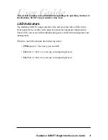
Page 9: ...single interface line card provides three LEDs on the front panel for the visible verification of unit status and proper functionality These LEDs can assist with troubleshooting and overall network di...

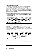
Page 10: ...Card B with LLR2 enabled will return a no link condition to its link partner Line Card A Because the line cards are designed with LLCF functionality the no link condition is carried forward to the swi...

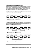
Page 11: ...that link loss forward to the switch hub which generates a trap to the management station The network administra tor can then determine the source of the problem Management Station Management Station...

Page 12: ...rise Switch Workgroup Hub Singlemode Links Multimode Links Switch Switch PC running Network Management Software Servers Enterprise Radiance R5000 Central Service Platform with SONET Single Interface L...

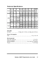
Page 13: ...u p n I r e w o P t a s X T t u p t u O r e w o P n i m X T t u p t u O r e w o P x a m r e w o P t e g d u B X T r w P n i m X R r w P n i m 3 C O 1 M T S M M 4 3 5 2 1 R 7 3 5 2 1 R m n 0 1 3 1 m k...

Page 14: ...provide reasonable protection against harmful interference when the equip ment is operated in a commercial environment This equipment generates uses and can radiate radio frequency energy and if not...

Page 15: ...ber and date of purchase To return a defective product for warranty coverage contact Metrobility Customer Service for a return materials authorization RMA number Send the defective product postage and...

Page 16: ...e at http www metrobility com support manuals htm Product Registration To register your product go to http www metrobility com support registration asp 25 Manchester Street Merrimack NH 03054 USA tel...

Reviews: