background image

22

  User Guide

Product Safety, EMC and Compliance Statements

This equipment complies with the following requirements:

• UL
• CSA
• EN60950 (safety CE)
• FCC Part 15, Class A
• EN55022 Class A (emissions CE)
• EN55024: 1998 (immunity)
• DOC Class A (emissions)
• Class 1 Laser Product

This product shall be handled, stored and disposed of in accordance with all
governing and applicable safety and environmental regulatory agency require-
ments.

The following FCC and Industry Canada compliance information is applicable
to North American customers only.

USA FCC Radio Frequency Interference Statement

This equipment has been tested and found to comply with the limits for a Class
A digital device, pursuant to Part 15 of the FCC Rules. These limits are designed
to provide reasonable protection against harmful interference when the equip-
ment is operated in a commercial environment. This equipment generates, uses
and can radiate radio frequency energy, and if not installed and used in accor-
dance with the instruction manual, may cause harmful interference to radio
communications. Operation of this equipment in a residential area is likely to
cause harmful interference in which case the user will be required to correct the
interference at his own expense.

Caution: Changes or modifications to this equipment not expressly approved by
the party responsible for compliance could void the user’s authority to operate
the equipment.

Canadian Radio Frequency Interference Statement

This Class A digital apparatus meets all requirements of the Canadian Interfer-
ence-Causing Equipment Regulations.

Cet appareil numérique de la classe A respecte toutes les exigences du
Réglement sur le matériel brouilleur du Canada.

Summary of Contents for RADIANCE R231-13

Page 1: ...M LK RX 100 BASE RX LK FX RX LK T X 100 BASE RX LK FX S M RX LK T X 100 BASE T X T X MAN FD PWR MAN FD PWR MAN FD PWR LK LBK FX MAN FD PWR RX LK 100 BASE LBK RX T X LBK LBK LBK LBK LBK LBK II x II x I...

Page 2: ...to FX multimode ST R231 16 ____ RJ 45 to FX singlemode ST with diagnostics R231 17 ____ RJ 45 to FX singlemode SC 40 km with diagnostics R231 1J_____ RJ 45 to FX singlemode SC 100 km with diagnostics...

Page 3: ...Forward LLCF 17 Link Loss Return LLR 18 Topology Solutions 19 Technical Specifications 20 Product Safety EMC and Compliance Statements 22 Warranty and Servicing 23 Metrobility Metrobility Optical Syst...

Page 4: ...such as the packet error rate and packet details The administrator can also conduct tests on the remote link without any bandwidth reduction and isolate problems to prevent downtime This end to end vi...

Page 5: ...te card s fiber port receiver Duplex auto negotiation on the copper port Half and full duplex support on the copper port Write protect to enable or disable a remote line card from controlling a locall...

Page 6: ...hes MDI II to MDI X Switch twisted pair ports only To eliminate the need for crossover cables the access line card has an MDI II to MDI X switch on its twisted pair port The switch is located on the c...

Page 7: ...e h T d e l b a s i d s i n o i t a i t o g e n o t u A x e l p u d 2 R L L P U t r o p c i t p o r e b i f e h t n o d e l b a n e s i n r u t e R s s o L k n i L N W O D t l u a f e d t r o p c i t...

Page 8: ...urther details Auto Negotiation Auto negotiation AN is only supported on the copper port Enable AN to establish a full duplex connection with another auto negotiating device or to force the port to ha...

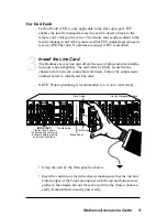
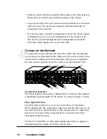
Page 9: ...o chassis before making network connections FX PWR RX RX LK LK M M FL TX TX 10 100 M M FX PWR RX RX LK LK M M FL TX TX 10 100 M M PWR M M OC 12 R X LK LK T X S M R X T X PWR M M OC 12 R X LK LK T X S...

Page 10: ...FD RX RX LK LK T X T X TX TX 10 100 RX LK LBK FX II x RX LK T X 100 BASE RX LK LBK FX II x RX LK T X LBK 100 BASE CWDM RX LK LBK II x RX LK T X 100 BASE MGT 10 LK AT C O N S O L E 1 PWR A B R ER FX P...

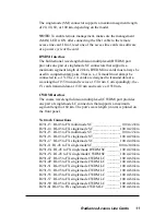
Page 11: ...ode LC connectors that supports a maximum segment length of 60 km The port s wavelength in nm is printed on the front panel Network Connections R231 13 RJ 45 to FX multimode SC ________________ 100 m...

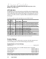
Page 12: ...r Green steady Unit is powered ON RX Receive Green blinking Port is receiving data LK Link Green steady Port has a valid link LBK Loopback Green steady Port is in loopback mode DIS Disable Green stead...

Page 13: ...ocation is applied to traffic received on the copper port When you set the TX bandwidth the allocation is applied to traffic transmitted on the copper port In addition to the bandwidth allocation you...

Page 14: ...smitted through the entire circuitry of the board not just the port in loopback mode This allows the entire circuit to be tested RMON statistics are incremented on both ports even though the physical...

Page 15: ...kts EtherStatsMulticastPkts EtherStatsCRCAlignErrors EtherStatsUndersizePkts EtherStatsFragments EtherStatsJabbers EtherStatsCollisions EtherStatsPkts64Octets EtherStatsPkts65to127Octets EtherStatsPkt...

Page 16: ...t i n o M r e w o P t u p n I l e d o M l a n o i t a r e p O e g n a R e t a r u c c A g n i r o t i n o M e g n a R s d l o h s e r h T p a r T g n i d a e R e r u l i a F 4 1 1 3 2 R 6 1 1 3 2 R m...

Page 17: ...carries that link loss forward to the switch hub which generates a trap to the management station The administrator can then determine the source of the problem Link Loss Carried Forward LED lit esta...

Page 18: ...ivity Units are shipped with the LLR function disabled DOWN If one of the optical conductors is bad as shown in the diagram box below the card with LLR enabled will return a no link condition to its l...

Page 19: ...diance Access Line Cards 19 Topology Solutions Radiance R5000 Remote Device Customer Premises CO POP SNMP Control Remote Communications Path Status Reporting Configuration Instructions Used Bandwidth...

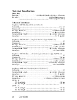
Page 20: ...Link Length __________________________ up to 40 km full duplex Cable Type _______________________________________ 9 125 m SM F O Singlemode F O Interface extended long haul distance support R231 1J C...

Page 21: ..._________________________ 31 dBm minimum Output Power _______________________ 23 5 dBm to 14 dBm 50 125 m _______________________ 20 dBm to 14 dBm 62 5 125 m Supported Link Length ____________________...

Page 22: ...reasonable protection against harmful interference when the equip ment is operated in a commercial environment This equipment generates uses and can radiate radio frequency energy and if not installe...

Page 23: ...se To return a defective product for warranty coverage contact Metrobility Customer Service for a return materials authorization RMA number Send the defective product postage and insurance prepaid to...

Page 24: ...e at http www metrobility com support manuals htm Product Registration To register your product go to http www metrobility com support registration asp 25 Manchester Street Merrimack NH 03054 USA tel...

Reviews: