


Radiance 10Mbps Single Interface Line Cards 9
LK
AT
FL
PWR
AT
LK
10 BASE
RX
LK
TX
FX
M
M
II
x
PWR
100
FD
RX
LK
T
X
TX
10/100
RX
LK
TX
FX
M
M
II
x
PWR
100
FD
RX
LK
T
X
TX
10/100
LK
AT
FL
R
X
PWR
FD
RX
10 BASE
II
x
PWR
100
FD
RX
RX
LK
LK
T
X
M
M
FL
TX
TX
10/100
II
x
II
x
PWR
100
FD
100
FD
RX
RX
LK
LK
T
X
T
X
TX
TX
10/100
RX
LK
TX
FX
M
M
II
x
PWR
100
FD
RX
LK
T
X
TX
10/100
RX
LK
TX
FX
M
M
II
x
PWR
100
FD
RX
LK
T
X
TX
10/100
FX
RX
LK
TX
M
M
II
x
PWR
100
FD
RX
LK
T
X
TX
10/100
MGT-10
LK
AT
C
O
N
S
O
L
E
1
PWR
A
B
R
ER
FX
PWR
RX
RX
LK
LK
M
M
FL
TX
TX
10/100
M
M
PWR
RX
R
X
LK
AT
M
M
TX
T
X
100 BASE
S
M
RX
LK
TX
FX
M
M
II
x
PWR
100
FD
RX
LK
T
X
TX
10/100
RX
LK
TX
FX
M
M
II
x
PWR
100
FD
RX
LK
T
X
TX
10/100
FX
PWR
RX
RX
LK
LK
M
M
FL
TX
TX
10/100
M
M
PWR
RX
RX
LK
LK
M
M
FL
TX
TX
10/100
FX
M
M
RX
LK
TX
FX
M
M
II
x
PWR
100
FD
RX
LK
T
X
TX
10/100
R
X
T
X
LK
TP
T
X
TP
R
X
T
X
M
M
M
M
LK
AT
2
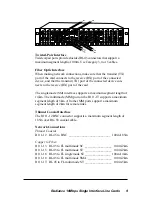
Twisted-Pair Interface
Twisted-pair ports provide shielded RJ-45 connectors that support a
maximum segment length of 100m. Use Category 3, 4 or 5 cables.
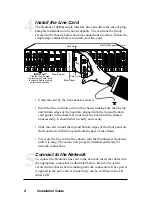
Fiber Optic Interface
When making network connections, make sure that the transmit (TX)
port of the card connects to the receive (RX) port of the connected
device, and that the transmit (TX) port of the connected device con-
nects to the receive (RX) port of the card.
The singlemode (SM) interface supports a maximum segment length of
14km. The multimode (MM) port on the R111-1T supports a maximum
segment length of 5km. All other MM ports support a maximum
segment length of 2km for remote links.
Thinnet Coaxial Interface
The R111-12 BNC connector supports a maximum segment length of
185m over RG-58 coaxial cable.
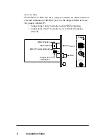
Network Connections
Thinnet Coaxial:
R111-12 RJ-45 to BNC __________________________ 100m/185m
Copper to Fiber:
R111-13 RJ-45 to FL multimode SC _________________ 100m/2km
R111-15 RJ-45 to FL multimode ST _________________ 100m/2km
R111-16 RJ-45 to FL singlemode ST ________________ 100m/14km
R111-18 RJ-45 to FL multimode SMA _______________ 100m/2km
R111-1T RJ-45 to FL multimode ST _________________ 100m/5km