background image

10

 Installation Guide

5

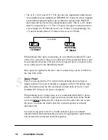
• The 2131-1X-01 and 2131-1Y-01 provide one singlemode bidirectional

wavelength division multiplexed (BWDM) SC connector which supports
a maximum segment length of up to 20km for remote links. BWDM
units must always be used in complementary pairs. That is, a-1X model
must be connected to a -1Y. The -1X unit is designed to transmit data at
a wavelength of 1550nm and receive at 1310nm. Correspondingly, the
-1Y unit transmits data at 1310nm and receives at 1550nm.

Metrobility

-1X Model

Metrobility

-1Y Model

up to 20km

When making fiber optic connections, be sure that the transmit (TX) port
of the 2131 connects to the receive (RX) port of the connected device; and
be sure that the transmit (TX) port of the connected device connects to the
receive (RX) port of the Metrobility model.

Once power is applied to the unit, correct connectivity can be verified via
the link (LK) LED.

Apply Power

Power is provided to the 2131 unit from the desktop universal power
supply module. This power module is equipped with a S760 hollow-type
plug for insertion into the DC jack located on the back of the 2131 and
standard IEC 320-type AC power receptacle.

When making power connections, it is recommended that the DC power
cord be connected to the DC input jack located on the back of the media
converter before making the AC connection to the outlet. Be sure to seat
the power cord into the strain relief clip to ensure against accidental
disconnection.

Upon receiving power, the 2131 media converter goes into normal
operation mode and automatically provides the appropriate signal transla-
tion between the connected network segments.

Summary of Contents for 2131-13-01

Page 1: ...ter TX RX MM PWR 100BASE FX 100BASE TX twister 2131 LK AT LK AT TX RX MM PWR 100BASE FX 100BASE TX twister 2131 LK AT LK AT TX RX SM PWR 100BASE FX 100BASE TX twister 2131 LK AT LK AT TX RX SM PWR 100BASE FX 100BASE TX twister 2131 LK AT LK AT TX RX SM LH PWR 100BASE FX 100BASE TX twister 2131 LK AT LK AT BWDM PWR 100BASE FX 100BASE TX twister 2131 LK AT LK AT ...

Page 2: ...131 1J 01 ____ TX to FX singlemode SC 100km universal AC 2131 1X 01 ____ TX to FX singlemode 1550 1310nm bidirectional wave length division multiplexed BWDM SC 2131 1Y 01 ____ TX to singlemode 1310 1550nm BWDM SC 2131 34 01 ____ FX multimode SC to FX singlemode SC universal AC 2131 36 01 ____ FX multimode SC to FX singlemode ST universal AC 2131 54 01 ____ FX multimode ST to FX singlemode SC unive...

Page 3: ...Carry Forward LLCF 13 Topology Solutions 14 Technical Specifications 16 Product Safety EMC and Compliance Statements 18 Warranty and Servicing 19 Metrobility Optical Systems the Metrobility Optical Systems logo and twister are trademarks of Metrobility Optical Systems Inc All others are trademarks of their respective owners The information contained in this document is assumed to be correct and cu...

Page 4: ...egrating a mixed media environment As LANs grow and evolve this technology provides an ideal solution for building effective migration strategies These IEEE 802 3u compliant media converters are compatible with Fast Ethernet devices from other leading network technology providers This increases the flexibil ity of your network configuration by ensuring reliable data transmission in multi vendor as...

Page 5: ...either side of the device The Metrobility 2131 provides the following key features A Link Loss Carry Forward LLCF enable disable switch is included to provide an easy means for troubleshooting a remote network connection Refer to the section of this guide titled Link Loss Carry Forward for more information All twisted pair ports are equipped with an MDI II to MDI X switch eliminating the need for ...

Page 6: ...Appropriate Location The 2131 media converter is intended for use in either office or industrial environments The unit must be located within six 6 feet of the AC power source being used and placed as far away as possible from electrical noise generating equipment such as copiers electrostatic printers and other motorized equipment If exposed twisted pair wiring is used nearby the wiring should be...

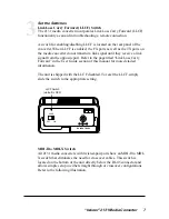
Page 7: ...opposite port Refer to the page titled Link Loss Carry Forward in the User Guide section of this manual for more detailed information The unit is shipped with the LLCF disabled To reset the LLCF simply slide the switch to the appropriate setting 3 PWR OFF ON DC INPUT 5VDC LLCF LLCF Switch default is OFF MDI II to MDI X Switch All 2131 media converters with twisted pair ports have an MDI II to MDI ...

Page 8: ...bject simply slide the switch in the direction of the appropriate symbol Use the following table as a guide A device that is wired straight through needs one crossover connection If the cable is straight through crossover the MDI II to MDI X Switch Setting should be X II A device that is wired crossover needs a parallel connection If the cable is straight through crossover the MDI II to MDI X Swit...

Page 9: ... 2km for remote links The 2131 14 01 provides one set of FX singlemode SC connectors and supports a maximum segment length of up to 15km for remote links The 2131 17 01 provides one set of FX singlemode SC connectors and supports a maximum segment length of up to 40km for remote links The 2131 1J 01 provides one set of FX singlemode SC connectors and supports a maximum segment length of up to 100k...

Page 10: ...f the connected device connects to the receive RX port of the Metrobility model Once power is applied to the unit correct connectivity can be verified via the link LK LED Apply Power Power is provided to the 2131 unit from the desktop universal power supply module This power module is equipped with a S760 hollow type plug for insertion into the DC jack located on the back of the 2131 and standard ...

Page 11: ...merican use a UL listed and CSA certified cord set consisting of a minimum 18 AWG type SVT or SJT three conductor cord a maximum of 15 feet in length and a parallel blade grounding type attachment plug rated 15A 125V AC 230V USA use a UL listed cord set consisting of a minimum No 18 AWG type SVT three conductor cord a maximum of 15 feet in length and a Tandem blade grounding type attachment plug r...

Page 12: ... status and proper functionality as well as aiding in troubleshooting and overall network diagnosis and management LEDs indicate the following PWR power the unit is ON and functioning in normal operation mode LK link twisted pair and fiber optic ports satisfactory link status on the respective port AT activity the port is receiving data Once power is applied to the unit correct connectivity can be...

Page 13: ...ve a link signal from the opposite port For example if LLCF is enabled and two 2131 media converters are connected via a fiber cable with nothing else connected to them the link LK LEDs do not illuminate When a valid link is established at the twisted pair port a complete connection is accomplished The diagram below shows a typical network configuration using 2131 media converters for remote conne...

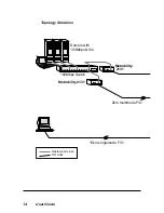
Page 14: ...14 User Guide Topology Solutions F O Links Twisted pair Links 100Mbps Switch 2km multimode F O 15km singlemode F O Servers with 100Mbps NICs Metrobility 2131 Metrobility 2131 ...

Page 15: ... twister 2131 Media Converter 15 Enterprise Switch 100Mbps Switch 2km multimode F O Metrobility 2131 Metrobility 2131 Enterprise ...

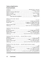
Page 16: ...__________________________________________________ ST or SC RX Input Sensitivity _______________________________ 31 dBm peak minimum Output Power ______________________________ 8 dBm to 15 dBm 9 125 µm Supported Link Length ______________________________ up to 15km full duplex Cable Type _________________________ 8 3 125 8 7 125 9 125 10 125 µm F O Singlemode Fiber Optic Interface long haul distan...

Page 17: ...____________________ 8 dBm to 15 dBm 9 125 µm Data Rate Data Rate _________________________________________ 100Mbps half duplex _________________________________________ 200Mbps full duplex Bit Delay ___________________________________________________ 40 bits Power Input ____________________________________________ 90 260V AC 50 60 Hz Output ________________________________________________ 5VDC 1 ...

Page 18: ...esigned to provide reasonable protection against harmful interference when the equipment is operated in a commercial environment This equipment generates uses and can radiate radio frequency energy and if not installed and used in accordance with the instruction manual may cause harmful interference to radio communications Operation of this equipment in a residential area is likely to cause harmfu...

Page 19: ... defective product for warranty coverage contact Metrobility Customer Service for a return materials authorization RMA number Send the defective product postage and insurance prepaid to the address provided to you by the Metrobility Technical Support Representative Failure to properly protect the product during shipping may void this warranty The Metrobility RMA number must be clearly on the outsi...

Page 20: ...btain additional copies of this manual contact your reseller or call 1 877 526 2278 or 1 603 880 1833 Product Registration To register your product go to http www metrobility com support registration cfm 25 Manchester Street Merrimack NH 03054 USA tel 1 603 880 1833 fax 1 603 594 2887 www metrobility com 5660 213113 001 H 6 02 ...

Reviews: