background image

18

 User Guide

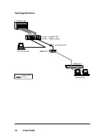
Topology Solutions

Enterprise Switch

F/O Links

Twisted-pair Links

10Mbps Hub 

2km multimode F/O

twister  2111

Lancast    Intelligent 7500
with R111 10Mbps modules

PC with fiber NIC

PCs with NICs

Summary of Contents for 2111-12-01

Page 1: ... 01 2111 13 B 2111 15 B twister 2111 10 Mbps Media Converter LINK PWR 10BASE 2 10BASE T twister 2111 ACT ON OFF TERM COL TX RX LK AT PWR 10BASE FL 10BASE T twister 2111 TX RX LK LK AT AT PWR 10BASE FL 10BASE T twister 2111 I I x LK AT I I x ...

Page 2: ...in any form or by any means manual electric electronic electromagnetic mechanical chemical optical or otherwise without prior explicit written permission of Metrobility Optical Systems Inc 1999 2005 Metrobility Optical Systems Inc All rights reserved Printed in USA Metrobility 10 Mbps twister Standalone Media Converters 2111 12 01 ____ RJ 45 to BNC 2111 13 B _____ RJ 45 to FL multimode SC 2111 15 ...

Page 3: ... User Guide 15 System LEDs 15 Transparency Mode 16 Topology Solutions 18 Technical Specifications 19 Product Safety EMC and Compliance Statements 20 Warranty and Servicing 21 Metrobility Optical Systems Metrobility Lancast and twister are registered trademarks of Metrobility Optical Systems Inc the Metrobility Optical Systems logo is a trademark of Metrobility Optical Systems Inc All others are tr...

Page 4: ...ntegration of 10BASE T Category 3 4 and 5 twisted pair segments with either multimode 10BASE FL fiber optic segments or thinnet coax in Ethernet environ ments To optimize your Ethernet network the 2111 media converter provides seamless operation in half or full duplex modes Full signal restoration with a low bit delay ensures accurate data transmission to and from LANs within an organization All s...

Page 5: ...h corner on the bottom of the twister 2111 Installing the feet provides an air gap which helps to cool the unit adds stability and prevents marring and scratching of the desktop surface Choose an Appropriate Location The twister 2111 media converter is intended for use in an office or industrial environment The unit must be located within six 6 feet of the AC power source being used and placed as ...

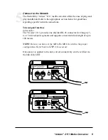
Page 6: ...NC port External termination is enabled when the switch is in the OFF position default Use this setting if the twister will be used in a daisy chain configuration or if you must use a BNC T connector and terminator for proper external termination Internal 50Ω termination is enabled when the switch is in the ON position To change the setting use a pointed object to slide the switch When internal te...

Page 7: ...efault the twister becomes completely transparent to the end devices connected to its two ports This allows the devices to perform auto negotiation directly with each other For most applications we recommend this mode of operation When TSP is disabled OFF you must manually configure the speed and duplex on both end devices to the same setting Refer to Transparency Mode for more information about t...

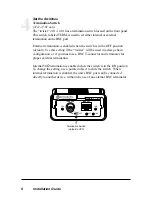
Page 8: ...witch All twister media converters with twisted pair ports have an MDI II to MDI X switch that eliminates the need for crossover cables The switch allows simple setup in either straight through or crossover configurations It is located on the bottom of the unit directly below the RJ 45 connector or on the front panel between the two ports Refer to the illustrations below When setting the MDI II to...

Page 9: ... twister 2111 provides one shielded RJ 45 connector for Category 3 4 or 5 twisted pair segments and supports a maximum link length of up to 100 meters NOTE Be sure you have set the MDI II to MDI X switch to the proper configuration Refer back to STEP 4 if necessary Once power is applied to the unit correct connectivity can be verified via the link LK LED 5 TX RX LK AT PWR 10BASE FL 10BASE T twiste...

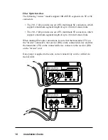
Page 10: ...ors which support a maximum segment length of up to 2 km for remote links When making fiber optic connections be sure that the transmitter TX on the twister connects to the receiver RX on the connected device and that the transmitter TX on the connected device connects to the receiver RX on the twister unit Once power is applied to the unit correct connectivity can be verified via the LK LED TX RX...

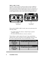
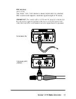
Page 11: ...h of 185 meters IMPORTANT The coaxial cable of a LAN must be properly terminated at the end of each segment regardless of the device used at the end of each cable One end of the two terminators on each segment must be grounded COL LINK PWR 10BASE 2 10BASE T twister 2111 ACT OFF TERM COL LINK PWR 10BASE 2 10BASE T twister 2111 ACT OFF TERM ON Termination ON Termination OFF default ...

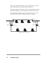
Page 12: ...t The example below illustrates how to connect the twister 2111 12 01 when the termination switch is disabled and when it is enabled Workstation Workstation Workstation Workstation Hub twister Termination OFF SEGMENT 1 0 5 meters min 185 meters max SEGMENT 2 0 5 meters min 185 meters max Workstation twister Termination ON UTP Cable up to 100 meters Workstation Hub twister Termination ON BNC Termin...

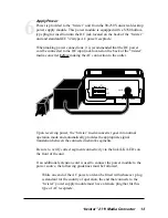
Page 13: ...AC connection to the outlet PWR DC INPUT 5VDC OFF ON TSP Upon receiving power the twister media converter goes into normal operation mode and automatically provides the appropriate signal translation between the connected network segments Be sure to verify correct segment connectivity via the link LK LEDs on the front of the unit If an additional extension cord is used to connect the power module ...

Page 14: ...V AC 230V USA use a UL listed cord set consisting of a minimum No 18 AWG type SVT three conductor cord 15 feet maximum length and a tandem blade grounding type attachment plug rated 15A 250V 240V outside USA use a cord set consisting of a minimum No 18 AWG cord and grounding type attachment plug rated 15A 250V The cord set should have the appropriate safety approvals for the country in which the t...

Page 15: ...well as aiding in troubleshoot ing and overall network diagnosis and management LEDs indicate the following PWR power the unit is receiving power and functioning normally LK link satisfactory link status on the respective port AT activity the respective port is receiving data COL collision detection of a collision condition and subsequent JAM packets generated on both segments Once power is applie...

Page 16: ...lex Switch Hub w SNMP Remote Device 2111 xx B twister LED lit established link LED unlit no link 2111 xx B twister TSP is ON TSP is ON Auto negotiation occurs end to end TX FX TX Management Station When the end devices have auto negotiation AN enabled a loss of link anywhere in the segment is propagated to both ends as shown in the diagram below This allows both end devices to become aware of any ...

Page 17: ...ter AN is OFF AN is OFF Link loss is forwarded TX FX TX TSP is ON TSP is ON Management Station When the Transparency Mode is disabled OFF you must manually configure the speed and duplex on both end devices to the same setting That is both end devices must be set to one of the following configurations 10 Mbps full duplex 10 Mbps half duplex ...

Page 18: ...8 User Guide Topology Solutions Enterprise Switch F O Links Twisted pair Links 10Mbps Hub 2km multimode F O twister 2111 Lancast Intelligent 7500 with R111 10Mbps modules PC with fiber NIC PCs with NICs ...

Page 19: ...wer _________________________ 21 8 dBm to 16 8 dBm 50 125 µm __________________________ 19 dBm to 14 dBm 62 5 125 µm Supported Link Length ______________________________ up to 2 km full duplex Cable Type _____________________________ 50 125 62 5 125 100 140 µm F O Thinnet Coax Interface 2111 12 01 Connector _____________________________________________ BNC receptacle Internal Transceiver _________...

Page 20: ...igned to provide reasonable protection against harmful interference when the equipment is operated in a commercial environment This equipment generates uses and can radiate radio frequency energy and if not installed and used in accordance with the instruction manual may cause harmful interference to radio communications Operation of this equipment in a residential area is likely to cause harmful ...

Page 21: ... defective product for warranty coverage contact Metrobility Customer Service for a return materials authorization RMA number Send the defective product postage and insurance prepaid to the address provided to you by the Metro bility Technical Support Representative Failure to properly protect the product during shipping may void this warranty The Metrobility RMA number must be clearly on the outs...

Page 22: ... at http www metrobility com support manuals htm Product Registration To register your product go to http www metrobility com support registration asp 25 Manchester Street Merrimack NH 03054 USA tel 1 603 880 1833 fax 1 603 594 2887 www metrobility com 5660 211112 001 M 6 05 ...

Reviews: