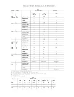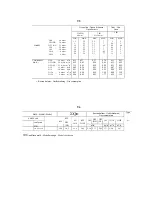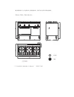
Gas Ranges (30361-00) 11/32
GB
INDEX
INSTALLATION INSTRUCTIONS
----------------------------------------------------------------------- page --- 12
WARNINGS
---------------------------------------------------------------------------------------------------------- page --- 12
INSTALLATION
------------------------------------------------------------------------------------------------------ page --- 12
Positioning
Assembly
In line union of the appliances
Connection to the gas piping
CONVERSION
TO
ANOTHER
TYPE
OF
GAS
------------------------------------------------------------------------ page --- 12
Replacement of nozzle and burner primary air adjustment
Replacement of gas cock minimum adjustment screw
Replacement of pilot burner nozzle
Replacement of gas preset adhesive label
START
-
UP
------------------------------------------------------------------------------------------------------------ page --- 12
Function check
Nominal heat input check
Inlet pressure check
ANALYSIS
OF
SEVERAL
FAILURES
--------------------------------------------------------------------------------- page --- 13
Difficult or lacking pilot ignition
Extinction of pilot burner flame during operation
Difficult or lacking burner ignition
Difficult or lacking temperature adjustment
REPLACEMENT
OF
PARTS
SUBJECT
TO
CHANGE
----------------------------------------------------------------- page --- 13
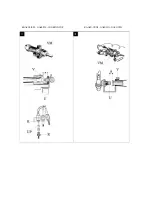
Burner, Pilotburner, Thermocouple
Gas cock of cooking hobs
Gas cock, Piezoelectric igniter of gas heated oven
Burner, thermocouple, Ignition spark plug of gas heated oven
Door seals
USE AND MAINTENANCE
---------------------------------------------------------------------------------- page --- 13
WARNINGS
----------------------------------------------------------------------------------------------------------- page --- 13
USE
------------------------------------------------------------------------------------------------------------------page --- 13
Cooker hob burners
Open burner ignition
Open burner extinction
Gas oven
Gas oven burner ignition
Gas oven burner extinction
CLEANING
AND
MAINTENANCE
------------------------------------------------------------------------------------ page --- 14
Cleaning oven chamber
LIST
OF
PARTS
SUBJECT
TO
REPLACEMENT
--------------------------------------------------------------------- page --- 14
Gas heating system

