background image

User Manual

EM606

000000

.

40

000000

.

40

000000

.

40

id    01

sl 0000

sH 0000

IMP

EXP

Kvarh

kWh

IMP

EXP

Kvarh

kWh

IMP

EXP

Kvarh

kWh

Hz

Kvar

KWA

Hz

Kvar

KVA

Hz

Kvar

KVA

ID Address

Serial number 
(high digit)

Serial number 
(low digit)

Communication 
Display (flashing)

II

I I

I I

I

I

I

I

I

I

I

I

I

I

I

I

I III

 ll l


l

l


l

l


l

l


l

l

l


l   ll 


888888

.

8

.

8

L1   59

.

6

MP

EXP

Kvarh

kWh

Hz

Kvar

KW

A

will flash to indicate that the value of 
current is negative

888888

.

40

L3      0

MP

EXP

Kvarh

kWh

Hz

Kvar

K A

V

will flash to indicate that the value of 
display is zero

l l


l

l


l

l


l

l


l

l

l


l   ll 


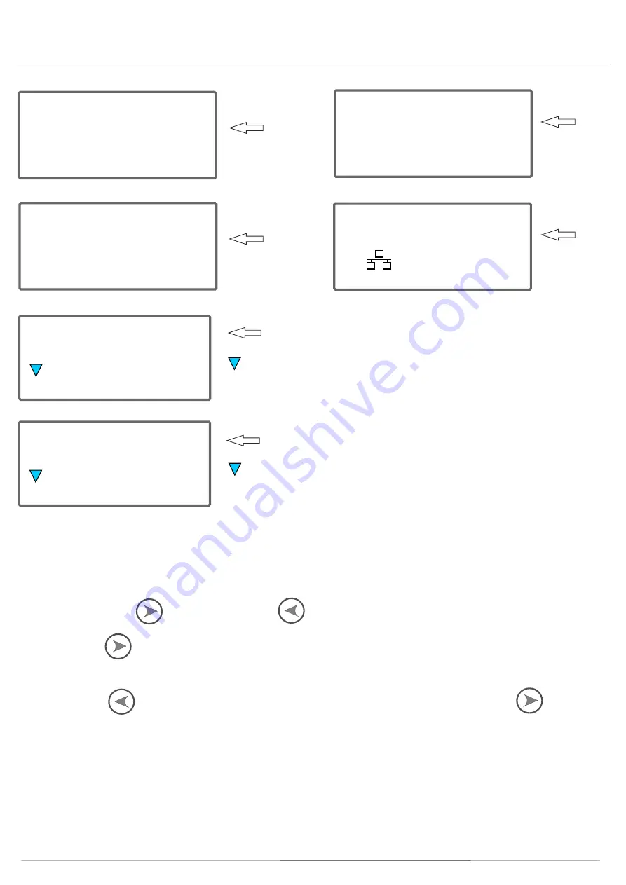
It is used as recording consumption and can’t be reset to zero. The reading accuracy is 1/100 kWh.

Button operation:

Right button is selection           , left button is program             .

Button selection               : one short press, lighting the backlight, then press one time show one parameter,

the order is as following: voltage of one phase, current of one phase, active power, reactive power, frequency, baud rate, 
ID address, serial number, in total 13 parameters, after one minute the backlight will close automatically.

Press  left  button             more  than  3  seconds  enter  in  code  confirmation  process,  use  right  button           choose the 
code number then use left button change the digit place, when finish code entering use left button press more than 3 seconds 
for confirmation then display show ID 01, use left button to change the display item, use right button to change the information. 
The items can be settled is : 1: ID;  2: baud rate,  3: number of display item (The number of Phase voltage, phase current, 
active power, reactive power, frequency, communication baud rate, ID address, serial number), 4 CT ratio setting for CT 
connection meter.

Pulse output

The EM606 Series DIN rail energy meter is equipped with a pulse output which is fully separated from the inside circuit. 
That generates pulses in proportion to the measured energy for accuracy testing.

Summary of Contents for EM606 M-Bus

Page 1: ...5 929 Three Phase 4 module energy meter METER SPECIFICATION 25 C to 55 C 30 C to 70 C Performance Criteria Operating Humidity 75 Storage Humidity 95 Operating Temperature Storage Temperature International Standard Active Energy Meters Class 1 B IEC62053 23 EN50470 1 3 Reactive Energy Meters Class 2 IEC62053 23 Voltage LN LL Phase 1 2 3 0 5 Amps Phase 1 2 3 0 5 PF Phase 1 2 3 0 2 Active Power Phase...

Page 2: ...munication indicator Communication symbol flashes Data Communication port Mbus Data Save 20 years when power off Dimensions Width x Height x Depth mm 17 5 x 112 x 60 Weight 0 4kg net M Bus communication specifications Bus type baud rate Range Downlink signal Uplink signal Cable Protocol Max Number of meters Note that the maximum number of meters is dependent on the converter baud rate the higher t...

Page 3: ... The over current protection device should comply with the specifications of the buildings electrical design and all local regulations This meter can be installed indoor directly or in a meter box which is waterproof outdoor subject to local codes and regulations To prevent tampering secure the meter with a padlock or a similar device The meter has to be installed against a wall which is fire resi...

Page 4: ... 11 V 12 V as the minimum bus voltage at any device must not be lower than 24 V 36 V 24 V 12 V The cable resistance therefore limits the maximum possible cable length from the MBus Master Repeater to the device with the largest distance away from it largest cable segment The cable segment length is the distance from the M Bus Master to the M Bus device furthest away NOTE The given maximum cable se...

Page 5: ...User Manual INSTALLATION DIAGRAM EM606 LINE 1 LINE 2 LINE 3 NEUTRAL NEUTRAL IN 28 29 27 26 30 31 25 24 32 33 23 22 34 35 21 20 L1 L1 L2 L2 L3 L3 N N BUS2 BUS1 SO K SUPPLY L LOAD METER S2 S1 Fused ...

Page 6: ...ricity is used the LED will flash red The more quickly LED flashes the more energy is being used Reading the Meter LCD numerical display 8 6 2 6 digits for the sub display items LCD Display MP EXP Kvarh kWh MP EXP Kvarh kWh Hz Kvar KWA MD Hz Kvar KWA Accumulated Energy Auto scroll only V I P PF Hz Comms Auto or Manual scroll Scroll Select Button Pulse Output Indicator Phase Failure Indicator Negat...

Page 7: ...h Total Reactive kWh Export Total Active kWh L1 Voltage L2 Voltage L3 Voltage 000000 40 0000000 8 l2 59 6 p 6 89 000000 40 pf 1 00 MP EXP Kvarh kWh MP EXP Kvarh kWh MP EXP Kvarh kWh 000000 00 l1 59 6 MP EXP Kvarh kWh Hz Kvar KWA 000000 40 l3 59 6 MP EXP Kvarh kWh Hz Kvar KWA Hz Kvar KWA Hz Kvar KWA L1 Current L2 Current L3 Current Active Power Power Factor 000000 40 f 50 MP EXP Kvarh kWh Hz Kvar K...

Page 8: ... the order is as following voltage of one phase current of one phase active power reactive power frequency baud rate ID address serial number in total 13 parameters after one minute the backlight will close automatically Press left button more than 3 seconds enter in code confirmation process use right button choose the code number then use left button change the digit place when finish code enter...

Page 9: ... 24 30 40 50 60 70 80 90 100 110 120 130 140 150 160 170 180 190 S 500 ie If you select CT ratio 100 it will display Ct100 To check it turn the meter off and then on again The 4th screen will display 5 500 yes Once you have set the CT ratios press and hold the PRG button for 5 seconds YES will display showing that the settings are now programmed Notes 1 Press and hold the SEL button to switch on t...

Page 10: ...he meter completes startup after it shows the CT ratio Press and hold the PRG button for 3 seconds the display will show PS 0000 Press the SEL button once so that the display changes to PS 0001 Press and hold the PRG button for 3 seconds to enter the password If the password was correct default 0001 the meter is now in programming mode The first item is Id which is the Mbus address and is in 2 dig...

Page 11: ...ly Still no response Check if the P red or P green consumption led is flashing 40 flashes of the LED at 400 pulses per kWh equals 0 1kWh Check the external voltage source Ui is 5 27V DC with a voltage meter Check if the connection is correct the 5 27V DC should be connected to the collector connection pin 28 or pin 30 and the signal wire S to the emitter connection pin 29 or 31 Please contact tech...

Reviews: