


5
HYDROS 21
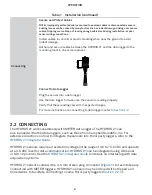
Ground
Digital communication
Power
Figure 1 Stereo plug connector
The HYDROS 21 comes standard with a 10-, 20-, or 40-m cable. In some instances, the cable
can be extended beyond 40 m by the user, but this is discouraged for a variety of reasons.
Please contact
for more details before extending or splicing cables.
NOTE: The HYDROS 21 vents the pressure transducer through the cable to atmospheric pressure. Long cable lengths
may cause a slow response to changes in atmospheric pressure; a maximum cable length of 40 m is recommended for
optimal venting.
2.2.1 CONNECT TO METER DATA LOGGER
The HYDROS 21 works most efficiently with METER ZENTRA series data loggers. Check the
for the most recent data logger firmware. Logger configuration
may be done using either ZENTRA Utility (desktop and mobile application) or ZENTRA Cloud
(web-based application for cell-enabled data loggers).
1. Plug the stereo plug connector into one of the sensor ports on the logger.
2. Use the appropriate software application to configure the chosen logger port for the
HYDROS 21. METER data loggers will automatically recognize HYDROS 21 sensors.
3. Set the measurement interval.
METER data loggers measure the HYDROS 21 every minute and return the average of the
1-min data across the chosen measurement interval.
HYDROS 21 data can be downloaded from METER data loggers using either ZENTRA Utility or
ZENTRA Cloud. Refer to the logger user manual for more information about these programs.
2.2.2 CONNECT TO A NON-METER DATA LOGGER
The HYDROS 21 can be purchased for use with non-METER (third party) data loggers. Refer
to the third-party logger manual for details on logger communications, power supply,
and ground ports. The
also provides detailed instructions on
connecting sensors to non-METER loggers.
HYDROS 21 sensors can be ordered with stripped and tinned (pigtail) wires for use with
screw terminals. Refer to the third-party logger manual for details on wiring.
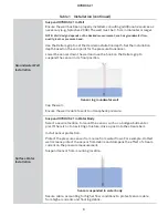
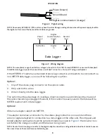
Connect the HYDROS 21 wires to the data logger as illustrated in
and
, with
the power supply wire (brown) connected to the excitation, the digital out wire (orange) to a
digital input, and the bare ground wire to ground.