5
5
CONNECTING THE UNIT
CAUTION: A 5-micron filter (TSD800-6), not included, must be installed with the unit to
ensure proper air filtration.
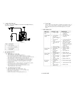
Figure 2.0
6
SETUP INSTRUCTIONS
Refer to Figure 1.0
6.1
Manual Dispense Cycle Setting:
1.
Turn on the unit by pressing the Power button (1)
2.
Press the Mode button (2) until “PURGE” appears on the Display.
3.
Turn up the air pressure by rotating the Air pressure regulator knob (6) until
the desired pressure is indicated on the Air pressure gauge (5)
4.
After filling the barrel or using pre-packaged adhesive, attach syringe to
receiver head assembly. Make certain that the syringe locks into place.
5.
Connect the plug end of the receiver head assembly to one of the air
dispense outlet (7)
6.
If vacuum “suck back” is needed, rotate the Vacuum regulator (8) counter
clockwise until the desired vacuum pressure is obtained
7.
Press and hold the Foot switch to activate dispensed cycle. (The
Purge/Manual Mode is now activated)
6.2
Automatic Dispense Cycle Setting:
1.
Push the Mode button (2) to select “TIMED” mode
2.
Rotate the Time control knob (9) to set desired dispense time
3.
Repeat step 3 to 6 in Section 6.1
4.
Depress Foot switch to activate timed dispensed cycle
Items
Description
1
To Air Source
2
Air Filter (Not included)
3
Power Adapter
4
Foot Switch
6
6.3
Cycle Counter
The cycle counter records the numbers of dispense cycle being activated. Up
to 65,535 cycles can be recorded. This number is shown at the lower right
hand corner of the LCD. Press the Counter Reset button (3) to clear the
counter.
7
TROUBLESHOOTING
PROBLEM
POSSIBLE CAUSE
CORRECTION
LCD does not
light
•
No power input
•
Check power cord
connections
•
Turn on power
System will not
actuate
•
Foot switch not
plugged in or
improperly plugged
in
•
Defective foot
switch
•
Broken wire or loose
connection inside
unit
•
Defective solenoid
•
Defective PC board
•
Check foot switch
connection
•
Foot switch needs to be
repaired or replaced
•
Unplug power cord and
disconnect air supply.
Remove cover and check
for broken wires or loose
connections
•
Replace solenoid
•
Replace PC board
System will not
pressurize
•
Insufficient air
pressure
•
Air hoses not
plugged in
•
Regulator defective
•
Increase air supply
pressure
•
Check connection
•
Replace regulator
System will not
pull vacuum
•
Vacuum setting is
too low
•
Defective solenoid
•
Defective vacuum
venturi
•
Defective vacuum
needle valve
•
Increase vacuum setting
•
Replace solenoid valve
•
Replace venture
•
Replace needle valve
Inconsistent
dispensing
•
Air bubbles in
adhesive
•
Dispense time is too
low
•
Dispense needle
started to clog
•
Reduce vacuum setting
•
Increase dispensing time
•
Replace needle
8
MAINTENANCE


