Metal Work Spa
- Via Segni 5 - 25062 Concesio (BS) Italy
ORIGINAL INSTRUCTIONS
VALVE IN NON-INTERLOCKED VERSION
INPUTS
solenoid pilot 0
0
1
1
p port 1
0 1 0
1
OUTPUTS p port 2
0
0
0
1
sensor 1
1
1
1
0
sensor 2
1
1
1
0
VALVE IN INTERLOCKED VERSION
INPUTS
solenoid pilot 0 0 0 0 1 1 1 1
p interlock
0 0 1 1 0 0 1 1
p port 1
0 1 0 1 0 1 0 1
OUTPUTS p port 2
0 0 0 0 0 0 0 1
sensor 1
1 1 1 1 1 1 0 0
sensor 2
1 1 1 1 1 1 0 0
1. Designation
Control valve for cutting off the air supply and relieving the air circuit connected to port 2.
2. Description
3/2 electropneumatic monostable double valve with spool monitoring.
3. Technical data
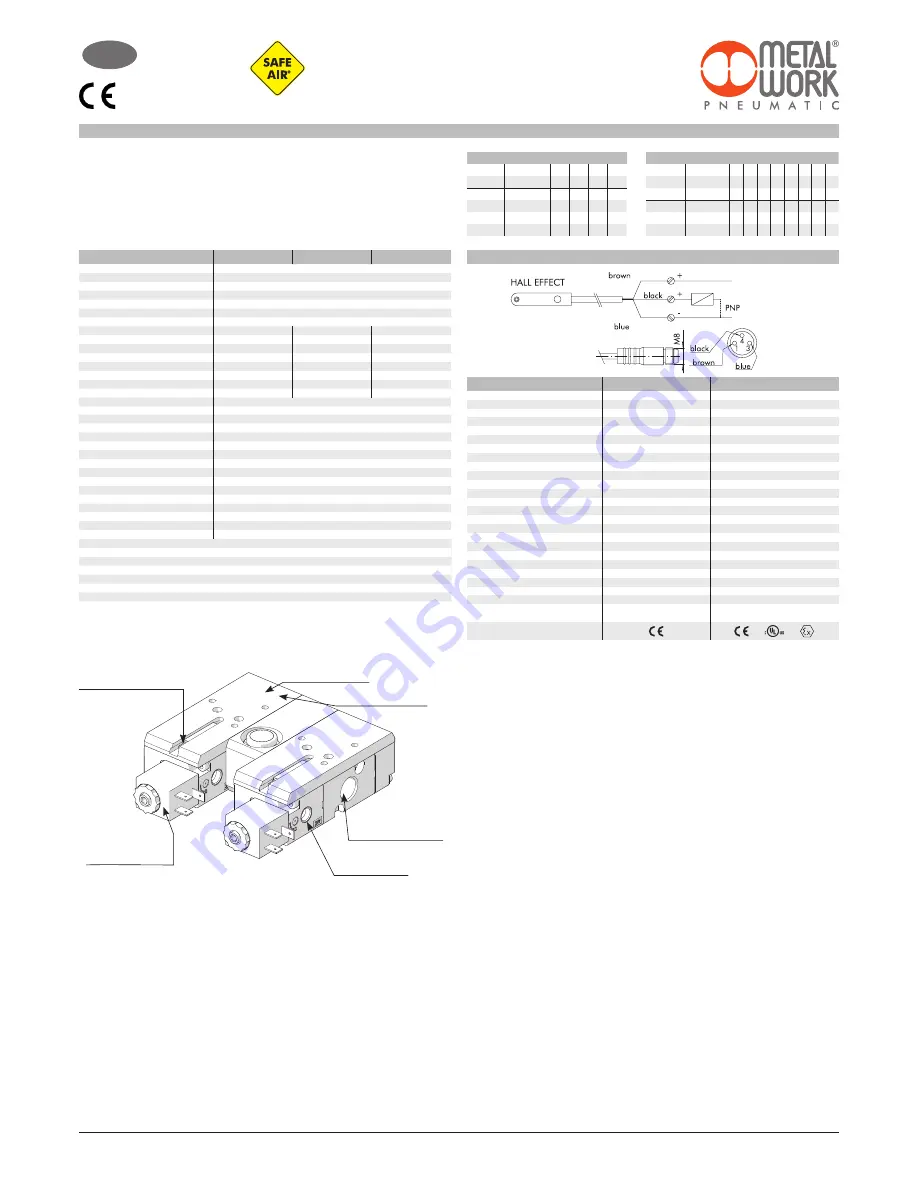
4. Installation instructions
Proceed as follows to install the valve:
- Mount the Metal Work actuating coils on the two solenoid pilots and secure them using the ring nuts
(max torque 1 Nm).;
- connect the air pipes to port 1 of valve 1 and to port 2 of valve 2, using the pneumatic fittings provided and
following the port numbering shown on the valve;
- supply power to the coils at the rated voltage. N.B. For correct operation, the two valves must be activated
simultaneously;
- supply power to the Hall-effect sensors and connect them to the diagnostic system. N.B. For correct operation,
the reading of the two sensors must be independent;
- supply port 1 of valve 1 with compressed air;
- check operation of the valves and sensors:
- if both coils are de-energized, port 1 of valve 1 is not connected with the pneumatic circuit of downstream,
port 2 of the valve 2 discharges (port3) and both sensors are ON;
- if both coils are energized, port 1 is connected to port 2, both sensors are OFF;
- do not mount 2 or more dual SAFE AIR® valves in adjacent positions; if dual side-by-side valves are mounted,
they must be spaced at least 40 mm.
- any ferromagnetic masses must be at least 40 mm from the sensor;
- prevent magnetic fields from creating disturbance in the sensor area.
Perform consistency checks based on the following tables, which relate the valve input and output statuses:
status 0: power/signal absent;
status 1: power/signal present.
When the double valve is in the safe status (one of the spools in the home position), at least one of the sensors is
ON (1).
5. Maintenance instructions
Before carrying out any maintenance operations it is recommended to use the personal protective equipment ,
and then to remember to switch off the electricity and compressed air supplies.
Check the silencers regularly for blockage.
For maintenance operations, it is advisable to return the valve to Metal Work for the necessary repairs.
6. Instructions to prevent residual risks
- The valve must be installed by a qualified technician
- Make sure the power cables do not get damaged during operation
- Make sure the power terminals are properly connected
- Check that the pipes are inserted properly before activating the air supply
- Check that the coils and sensors are correctly wired
- Cut off the power and the air supply prior to maintenance interventions
- If the safety function (safe relief) is used less than once a month, it is advisable to conduct a monthly function test
7. Disposal instructions
The product must be dismantled and disposed of in accordance with the regulations in force in the country in which
the product is used.
TECHNICAL DATA SENSOR
Type of contact
Switch
Supply voltage (Ub)
V
Power
W
Voltage variation
Voltage drop
V
Input current
mA
Output current
mA
Switching frequency
Hz
Short-circuit protection
Over-voltage suppression
Polarity inversion protection
EMC
LED display
Magnetic sensitivity
Repeatability
Degree of protection (EN 60529)
Vibration and shock resistance
Temperature range °C
Sensor capsule material
2.5 m/2 m connecting cable
Connecting cable with M8x1
Wire NO.
Category ATEX
Certifications
ATEX
EFFECT HALL
EFFECT HALL
N.O.
N.O.
PNP
PNP
from
10 to 30 DC
from
18 to 30 DC
3
#
1.7
#
10% of Ub
#
10% of Ub
#
2
#
2.2
#
10
#
10
#
100
#
70
#
5000
1000
Yes
Yes
Yes
Yes
Yes
Yes
EN 60 947-5-2
EN 60 947-5-2
Yellow
Yellow
2.8 mT ± 25%
2.6
#
0.1 mT
#
0.1 (Ub and ta fixed)
IP 67
IP 68, IP 69K
30 g, 11 ms, from 10 to 55 Hz, 1 mm
30 g, 11 ms, from 10 to 55 Hz, 1 mm
from
-25 to +75
from
-20 to +45
PA66 + PA6I/6T
PA
PVC; 3 x 0,14 mm
2
PVC; 3 x 0,12 mm
2
Polyurethane; 3 x 0,14 mm
2
-
3
3
-
II 3G Ex nA op is IIC T4 Gc X
II 3D EX tc IIIC T135°C Dc IP67 X
WIRING DIAGRAM SENSOR
OPERATING INSTRUCTIONS
FOR VALVE DOUBLE
SERIE 70 VALVES SAFE AIR
®
GB
1/8”
1/4”
3/8”
Fluid
Filtered unlubricated air (50µm); lubrication, if used, must be continuous
Operation
3/2 monostable
Operating pressure:
bar
- non-assisted
2.5 ÷ 10
- pilot-assisted
Vuoto ÷ 10
Minimum pilot pressure
bar
2.5
Operating temperature range
°C
-10 ÷ +60 (-10 ÷ + 45 for Atex version)
Conductance C
Nl/min · bar
80
202
346
Critical ratio b
bar/bar
0.35
0.11
0.24
Flow rate at 6.3 bar ∆p 0.5 bar
Nl/min
261
561
1038
Flow rate at 6.3 bar ∆p 1 bar
Nl/min
358
778
1433
TRA/TRR at 6.3 bar
ms/ms
28/35
38/45
50/72
Conductance C on relief
Nl/min · bar
132.96
228.52
491.66
Critical ratio b on relief
bar/bar
0.27
0.21
0.21
Flow rate on free exhaust 6.3 bar
Nl/min
930
1700
3550
Installation
any position
Assembly
In line
Manual actuator
Monostable
Recommended lubricant
ISO and UNI FD 22
Compatibility with oils
See webpage www.metalwork.it/eng/materiali_compatibilita.html
Coils
22 mm side, ø 8 hole
2 W - 12 VDC, 24 VDC
3.5 VA - 24 VAC, 110 VAC, 220 VA 50/60 Hz
Certified EN 60204.1 and VDE 0580 (*)
Max coil ring nut torque
Nm
1
Class of protection
IP65 with coil and connector mounted
Noise level
Max. 78 dBA with silenced relief
B10d
50 x 10
6
cicli
Category - ISO EN 13849
4
DC
High (99 %)
PL - ISO EN 13849
Suitable for use in safety circuits up to PL=e
* To avoid malfunctions, we recommend using Metal Work accessories.
Mount the coil on the
pilot and tighten the
locking nut (max 1 Nm)
The port number is shown
on valve
The electrical connection of the
sensor must be as indicated
Check the order code is
correct
Connect the air tubes to
the base using pneumatic
fittings
Pilot (only SES
versions)


