36
ATTENTION
(for versions 1250/2500/3750/5000)
Since current dispersion towards earth of all the loads merges in the UPS protection wire (earth wire), it is
essential to check that the sum of these currents does not exceed 2.7 mA, according to standard EN
50091-1-1, for safety reasons.
Precautions for installation
• Electrical connections should only be done by trained personnel
• Do not modify the electric cables supplied
• Make sure that the mains outlet is connected securely to an earth circuit
• The mains outlet, or the circuit breaker, must be installed near the appliance and must be easily
accessible
WARNING
Your UPS is fitted with a circuit to protect it against the risk of incorrect connections. This eventuality will be indicated
by means of its red warning light, lit without flashing, and the continuous sounding of its internal buzzer. Should you
note this signal immediately after switching the UPS on, switch it off and remove the power supply plug immediately.
3 - Installation
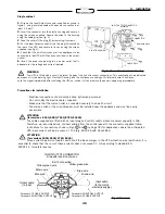
Fig. 4 Terminals
INPUT-OUTPUT CONNECTOR
Side with insertion of wires
Earth connection
Yellow-green wire
Blue wire
Blue wire
Yellow-green wire
Brown wire
Brown wire
Terminal n
°
1 PHASE OUTPUT
Terminal n
°
2 NEUTRAL OUTPUT
Terminal n
°
4 NEUTRAL OUTPUT
Terminal n
°
5 PHASE OUTPUT
Output cable
(to load)
Input cable
(to the mains
electricity supply)
Fig. 3 Connection terminals housing
Single cabinet
1.
Wire up the Input-Output connector supplied as shown in
figure 3, using insulated cable with wires whose section is at
least 2.5 mm2.
2.
Insert the connector into the plastic housing and secure it
using the screws supplied. Secure the wires to the housing
using the cable grip (see fig. 3).
3.
Take the cover off the plug [9] by removing its screws.
4.
Put the Input-Output connector into the plug [9] located on
the rear of the UPS, and secure to its case using the screws
supplied (see fig. 2).
5.
Check that the on/off switches of all the appliances to be
connected to the UPS are OFF and connect them to the output
socket.
6.
Insert the power supply plug into a power outlet that is
adequate for the voltage and current required.
INPUT-OUTPUT CONNECTOR
Assembly
CONNECTOR
Reference notch
CABLE GRIP
PLASTIC HOUSING
!
!
ATTENTION
(for versions 5000/6250/7500/8750/10000)
The cables supplied are fitted with an input plug and outlet sockets whose maximum capacity is 16A.
Therefore, we recommend use of direct cabling from the control panel to the connector supplied (follow
instructions for connections shown in Figs. 3 and 4 on Page 39) for applications where the anticipated
UPS input current will be in excess of 13A (e.g. 5000 VA with Vinn=184V)
!
Summary of Contents for MEGALINE 1250 RACK
Page 80: ......

