4
114A5578A
QUICK REFERENCE GUIDE
COMMISSIONING AND PROGRAMMING
THE PROTECTOR SYSTEM™ (IR BEAMS) (OPTIONAL)
NOTE: Merlin strongly recommends that The Protector System™ (IR Beams) be installed on all gate openers.
Compatible Protector System™ (IR Beams) are 772ANZ and GPS15 Monitored Safety Beams.
The Protector System™ (IR Beams) can be configured to function differently when connected to IR1, IR2 or IR3 inputs.
1. Connect the Protector System™ (IR Beams) to IR1/GND or IR2/GND and or IR3/GND.
2. The IR Beams can be configured to monitor in the open or close direction or both (see section 23 IR Behaviour).
3. The IR Beams will automatically learn to the opener after they have been connected and are default to monitor the close direction.
4. If you need to remove the IRs, you will need to unlearn them from the opener. This is done by switching off the mains power off and
on again twice.
INSTALL ENTRAPMENT DEVICES
PROGRAMMING - INITIAL SETUP
1
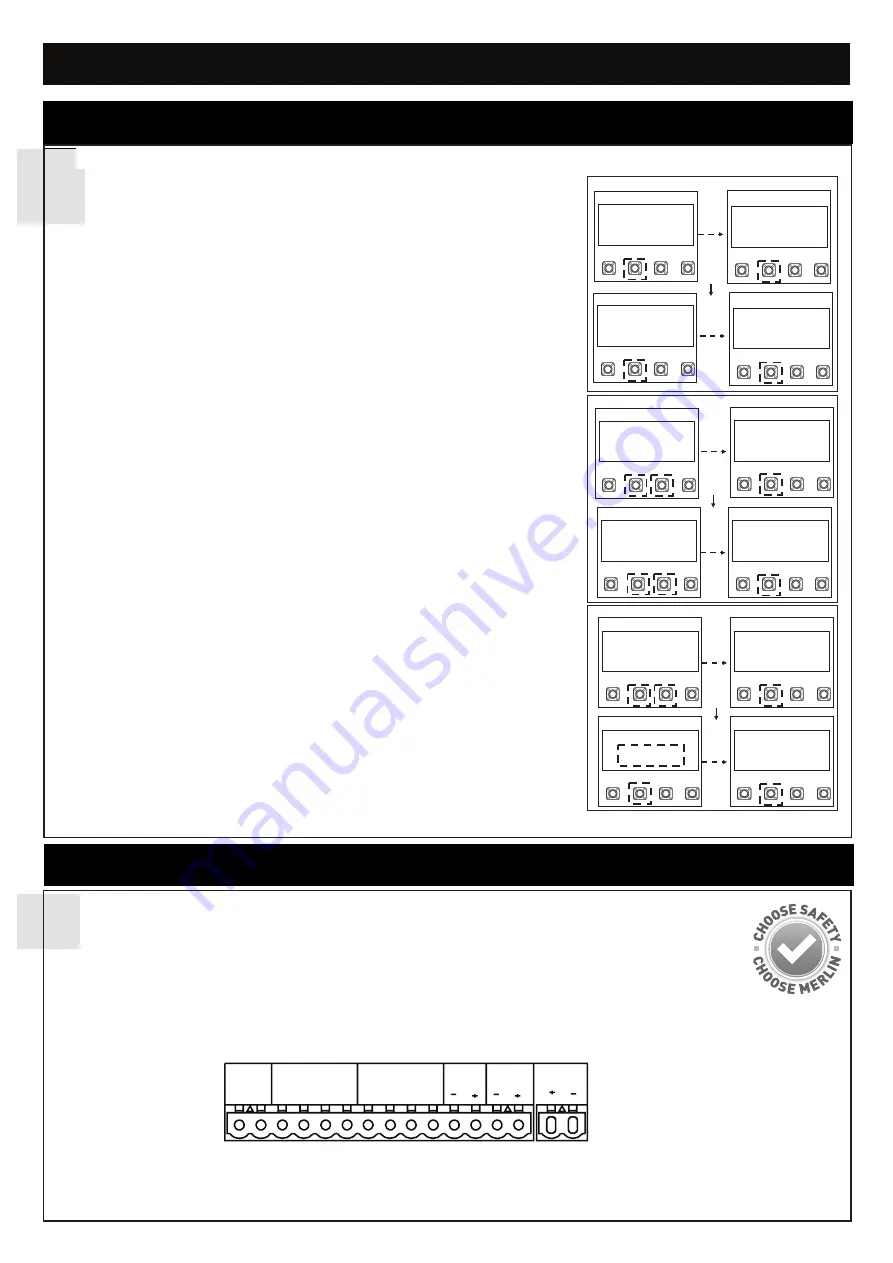
Energise the opener. Release the opener manual release with the key, and move the
gate(s) to a mid open position. Re-engage the manual release.
The LCD screen will display the Cycle count.
1. Press and hold the “P” button for approximately 5 seconds to enter into the Main
Menu. MAIN MENU SELECT APPLICATION will be displayed on the LCD.
2. Press the “P” button once to enter this Menu option.
3. Use the “+” or “-” to scroll though the motor application options. When
“ARTICULATED ARM SINGLE OR ARTICULATED ARM DUAL” is shown, press the
“P” button to select. The screen will change to show MAIN MENU SELECT
APPLICATION.
4. Press the “+” button once to scroll to the next menu option. “MAIN MENU
DIRECTION MOTOR1” will be displayed on the LCD.
5. Press the “P” button to select. The screen will change to show PRESS & HOLD “+”
GATE OPENING? YES “P”, NO “S”.
6. Press and hold “+”. The gate will start to move.
a) If it moves in the OPEN direction, press “P” to confirm”. The screen will change
to show MAIN MENU DIRECTION MOTOR1
b) If the gate moves in the CLOSE direction, press “S” to confirm. The screen will
change to
EXECUTE MOTOR DIRECTION CHANGE.
Press “P” to confirm.
Once the direction has been confirmed, the screen will change to MAIN MENU
DIRECTION MOTOR. If there is a second slide gate opener to be setup, press the
”+” button to scroll to the next menu option “MAIN MENU DIRECTION MOTOR2
and follow the steps 5 and 6.
7. Press the “+” button once to scroll to the next menu option. “MAIN MENU
LIMIT&FORCE LEARN” will be displayed on the LCD.
8. Press the “P” button to select.
The gate will start to move.
The screen will change
and LIMIT&FORCE LEARN will flash on the screen.
9. Once complete, the gate will stop moving and the screen will change to CYCLES:
000,000 STANDBY GATE CLOSED.
Initial setup is now complete. The opener will now operate using default Basic Settings.
NOTE: If the LIMIT&FORCE LEARN setup needs to be stopped, press the “S”
button. The Screen will display LIMIT&FORCE LEARN INTERRUPTED. After 5
seconds, the screen will display LIMIT&FORCE LEARN. Repeat step 8 to
complete basic setup.
EDGE
SE SE
IR SENSOR
GND IR3 IR2 IR1
COMMAND
GND IN3 IN2 IN1
FLA
E-LK
SPEC
S
P
+
-
ARTICULATED ARM
SINGLE
S
P
+
-
S
P
+
-
MAIN MENU
DIRECTION MOTOR1
PRESS & HOLD “+”
GATE OPENING?
YES “P”, NO “S”
S
P
+
-
MAIN MENU
DIRECTION MOTOR1
S
P
+
-
MAIN MENU
SELECT
APPLCATION
S
P
+
-
CYCLES: 000, 000
BEGIN SETUP
S
P
+
-
MAIN MENU
SELECT
APPLCATION
S
P
+
-
MAIN MENU
SELECT
APPLCATION
S
P
+
-
MAIN MENU
LIMITED & FORCE
LEARN
S
P
+
-
MAIN MENU
SELECT
APPLCATION
S
P
+
-
MAIN MENU
LIMITED & FORCE
LEARN
S
P
+
-
CYCLES 000,000
STANDBY
GATE CLOSED
figure 1
figure 2
figure 3
EDGE SENSOR
The Edge sensor can only be connected to the Edge inputs.
1. Remove the 8.2k resistor from the Edge inputs.
2. Connect the 8.2k compatible edge sensor to the Edge inputs.


