


Merlin Equipment: PowerGuard Lite manual V2.2 10/15
Page 7
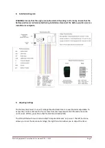
8.
Installation Diagram:
WARNING! Ensure that the engine cannot be started if working in it’s vicinity. Ensure that the
battery positive (+) is disconnected during installation. Reconnect the battery positive (+) once
installation is complete.
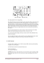
9.
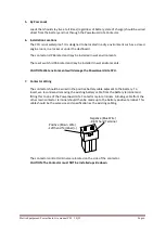
Adjusting Settings
The battery
disconnect (‘cut
-out
’)
voltage threshold and timer are user/installer adjustable. To
access the controls, remove the four screws from the PowerGuard Lite CPU and remove the
unit’s cover. Within, you will see the Printed Circuit Board (PCB).
The PCB is fitted with two
controls called ‘
trim potentiometer
’
or ‘pre
-
set’
. The left hand one
allows you to set the disconnect voltage, the right hand one allows you to adjust the timer.


