Index
Introduction ...................................................................................... P1
Service Guide .................................................................................... P1
2.1.
How to replace or repair the
Seat Assembly
...........................................
P1
2.1.1. To replace the seat body ........................................................................................... P1
2.1.2. To replace the armrest assembly............................................................................... P1
2.1.3. To replace the seat base plate assembly .................................................................... P3
2.2.
How to replace or repair the
Battery Pack Assembly
.............................
P5
2.2.1. To replace the lower cover assembly ........................................................................ P3
2.2.2. To replace the upper cover assembly ........................................................................ P3
2.3.
How to replace or repair the
Rear Section Assembly
.............................
P4
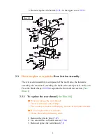
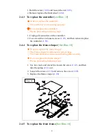
2.3.1. To replace
the rear shroud ........................................................................................ P5
2.3.2. To replace the anti-tip wheel .................................................................................... P5
2.3.3. To replace the driven wheel assembly ...................................................................... P5
2.3.4. To replace the transaxle assembly ............................................................................ P5
2.3.5. To replace the rear frame ......................................................................................... P7
2.4.
How to replace or repair the
Front Section Assembly
............................
P8
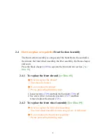
2.4.1. To replace
the front shroud ...................................................................................... P8
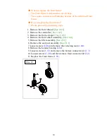
2.4.2. To replace the front wheel assembly ........................................................................ P8
2.4.3. To replace the controller .......................................................................................... P8
2.4.4. To replace
the frame clasper .................................................................................... P9
2.4.5. To replace the front frame ........................................................................................ P9
2.5.
How to replace or repair the
Tiller Assembly
.........................................
P11
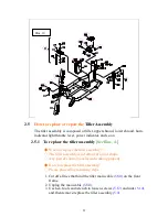
2.5.1. To replace
the tiller assembly ................................................................................... P11
2.5.2. To remove the lower cover ....................................................................................... P11
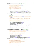
2.5.3. To replace the throttle lever or variable resistance .................................................... P11
2.5.4. To replace the horn button or buzzer ........................................................................ P12
2.5.5. To replace the power indicator ................................................................................. P12
2.5.6. To replace the knob or potentiometer ....................................................................... P12
2.5.7. To replace the key and key switch ............................................................................ P12
2.5.8. To replace the lower cover ....................................................................................... P13
The numbers shown in this service manual is just for reference. The part
numbers should be in accordance with current exploded drawing
Summary of Contents for S237
Page 1: ...Merits S539 237 Service Manual Jan 27 2010V1...
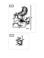
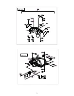
Page 4: ...2 Illus 01 Illus 02...
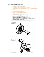
Page 8: ...6 Illus 04 Illus 05...


