TP-08122
(16579/22882)
Issued 09-09
Printed in USA
Copyright ArvinMeritor, Inc., 2009
Page 5
Display Control
The display control includes alarm volume adjustment, LCD
brightness and LCD contrast adjustment capability and U.S./metric
unit conversion. The display will store the last display control
settings in non-volatile memory (remains stored in memory when
turned off). The display background is green. Figure 13.
Figure 13
앫
Press the UP/DOWN keys to scroll through the menu list.
앫
Press the MODE key to select the value to be changed.
앫
In edit mode, the screen will display **EDIT VALUE**.
앫
Press the UP/DOWN keys to change the value setting.
앫
Press the MODE key to save the setting.
앫
Press the MODE key again to advance to the Radar Alignment
screen.
Radar Alignment
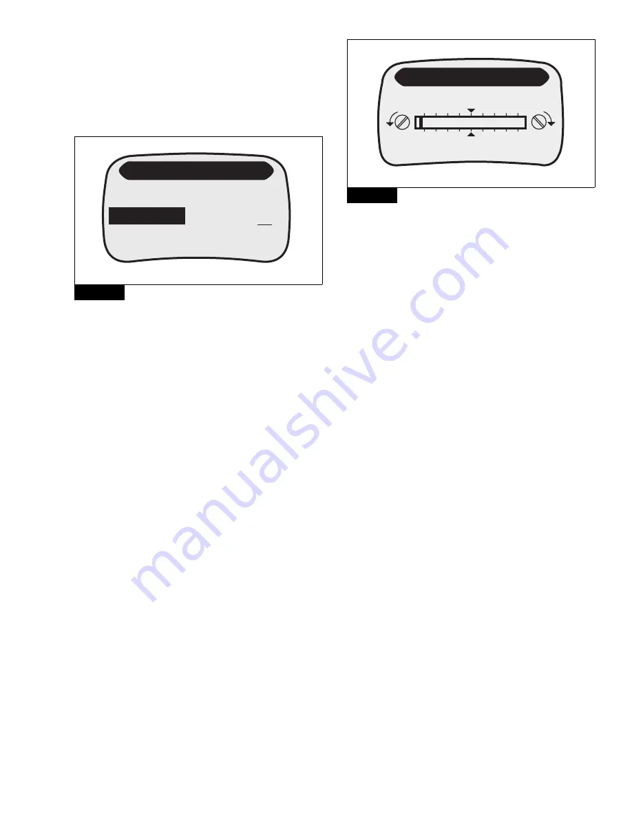
The display provides visual indication of the alignment state of the
radar sensor, the distance of the current radar target to the vehicle,
and the estimated vehicle mass. Figure 14.
앫
The upper section of the display shows the Target Distance.
When there is no target detected as in CWS Standby or ACC
Standby, the Distance to Target will display NA.
앫
The middle section of the display provides a horizontal bar graph
showing the horizontal angle to the target vehicle. When
following a vehicle on a smooth, straight road, the indicator bar
should hover around the center indicator arrows.
앫
The lower section of the display shows the estimated vehicle
mass determined by the ABS controller. Mass will reset to “Not
Available” if the data is not available (e.g., if the vehicle is not
moving for several minutes). Version 0.12 and version 0.23
software display 144,478 lb (65 535 kg) when mass is not
available.
Figure 14
The background color changes while in the Radar Alignment screen
to indicate the radar target status.
앫
The display background is blue when the radar is searching.
앫
The display background is green when the radar is tracking a
vehicle.
If radar sensor alignment is required, contact the vehicle
manufacturer dealer as soon as possible. Refer to Maintenance
Manual MM-0951 for radar sensor alignment instructions.
NOTE:
This is the only additional feature screen that will remain
active longer than one minute if no key is pressed.
Press the MODE key to advance to the ACC Function/Component
Test Menu.
ACC Function/Component Test Menu
The component test screen provides a method of verifying correct
operation of several system components and is a valuable tool to
diagnose OnGuard™ system errors The display background is blue.
Depending on the release level of the display, the header of the
display will read “ACC FUNCTION” or “COMPONENT TEST.” There
may be other small differences in the display terminology and the
sequence of menu items.
The ACC Function/Component Test screen will provide access to the
following components. Figure 15.
Press the UP/DOWN keys to scroll through the list. Press the MODE
key to advance to the Software Version screen.
Figure 13
4007352
a
DISPLAY CONTROL
Alarm Volume
10
Alarm Tone
4
LCD Intensity
9
Figure 14
4007151
a
Target Distance
N/A
RSC Mass Est
N/A
RADAR ALIGNMENT
Summary of Contents for OnGuard Display
Page 10: ...Notes...
Page 11: ......


