background image

29 


POWER 

SUPPLY


Anubis can be powered from a DC Power Supply (12V) and/or from PoE (Power over Ethernet).  
 

Using the 

DC power 

supply source


1. First connect the included Power Supply Mains adapter to an AC outlet.  

Note: The DC power source can also be coming from a 12V battery.


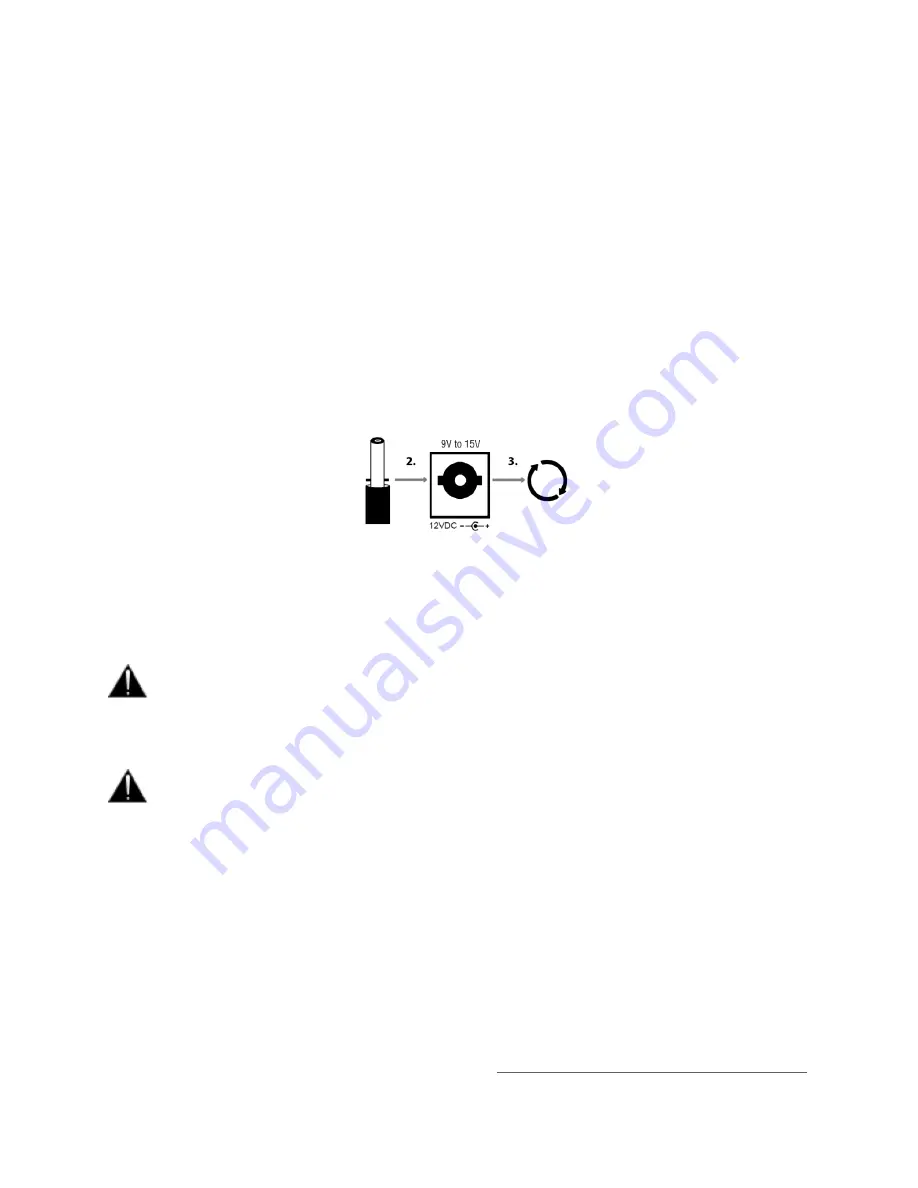
2. Connect the Power Supply to the rear panel of your Anubis.  

*

 The Locking Power Supply requires that you align the two tabs on the power cable's connector to the 

notches on the Anubis input male connector. 
Then rotate the barrel clockwise until latched, this will secure the connection and prevent accidental 
disconnection or a bad electrical contact. 


* The Locking Power Supply option is no longer manufactured as of the Anubis serials: 
A600640 (Pro) and above 
A650300 (Premium) and above.  
The Anubis Locking Power Supply accessory remains optional at ordering.  
Contact your Merging local sales representant for more details. 


The DC power input accepts voltages from 9V to 15V, with a maximum power consumption of 
18W. Do not exceed the maximum DC input voltage or the unit may be damaged. Merging highly 
recommends using the 12V power supply provided with Anubis. 


Check that the power cable has the correct plug for the power outlet to which it will be connected. 
If the wrong Mains cable has been supplied, do not attempt to modify it but contact your Merging 
Technologies dealer for a replacement.


Using the 

Power-over-Ethernet (PoE) source


Anubis can alternatively be powered from PoE (Power over Ethernet) or in parallel to the DC Power, if 
redundancy is required. 
PoE requirements:  


A suitable PoE+ equipped switch and/or external midspan PoE+ injector  


IEEE 802.3at class 0 Power-over-Ethernet standard 


37.0 V (Min) 

 48.0 V (Typical) - 57.0 V (Max) @ 1

2 A


Note: Recommended PoE Switches are available 

RAVENNA/AES67 Certified Network Switches


Summary of Contents for Anubis Premium

Page 1: ...USER MANUAL V21 07 2020...

Page 2: ...2...

Page 3: ...on 17 TOP PANEL 17 BACK PANEL 19 FRONT PANEL 21 ANUBIS ANALOGUE I O BLOCK DIAGRAM 22 HOW TO CONNECT MERGING ANUBIS 23 Connecting the Ethernet cable to the Network for RAVENNA use 23 How to connect a b...

Page 4: ...gnal flow 67 INFO Settings 80 DEBUG Settings 80 EXIT Settings 81 ANUBIS MONITOR MISSION CONTROL 82 Sources vs Monitors Fundamentals 84 Different Monitor types 85 MONITOR PAGE 87 Downmix Table 91 METER...

Page 5: ...Open the Remote Web User Interface 115 Web Access Source and Monitor Renaming 117 Web Access PreAmps Remote Control 118 Web Access Settings 121 Tablets Remote Access Using the Anubis IP Address 122 AN...

Page 6: ...of the MERGING ANUBIS We encourage you to familiarize yourself with the features applications and connection procedures before setting up your MERGING ANUBIS To ensure the safe operation of your Anub...

Page 7: ...not operate at a high volume level or at a level that is uncomfortable If you experience any hearing loss or ringing in the ears you should consult an audiologist 5 The product should be located so th...

Page 8: ...Merging Technologies makes no warranties express or implied regarding the MERGING ANUBIS embedded software its quality performance merchantability or fitness for a particular purpose The software is...

Page 9: ...f this equipment does cause harmful interference to radio or television reception which can be determined by turning the equipment off and on the user is encouraged to try to correct the interference...

Page 10: ...15 A at 230V Standards EN 55103 1 2009 EN 55103 2 2009 EN 61000 3 2 2006 A1 A2 EN 61000 3 3 2008 Detailed specifications of the tested and certified product are shown in the following Test Report Test...

Page 11: ...outside maximum rating 2 Products on which warranty stickers or product serial numbers have been removed altered or rendered illegible 3 The cost of installations removal or reinstallation 4 Damages...

Page 12: ...enefit is that if equipment runs cool it is usually also a guarantee of longevity and long term reliability Package Content If the shipping carton shows any signs of damage please inform your Merging...

Page 13: ...olving long life product with multiple missions upcoming Merging class of its own sound quality Ethernet with RAVENNA interface allows asynchronous data transfer with computer audio systems and allows...

Page 14: ...cate of the input channel at a different input gain level for backup or peak safety recording Instrument Line inputs Two Instrument Line inputs on front panel Can be used for Hi Z instruments or Line...

Page 15: ...a Bass management Instant access dedicated soft buttons And more Power over Ethernet supplied IEEE 802 3at compliant GPIO general purpose input output for studio e g Record light control or live e g F...

Page 16: ...f the shelf Gigabit switches and other IT technology to become a node on a LAN From that point any other RAVENNA node can receive information from and deliver information to any combination of RAVENNA...

Page 17: ...it could permanently damage the microphone 3 Speaker set A selector Select the Speaker A to activate this monitor set it will be activated once button is lit The monitor set can be configured from th...

Page 18: ...ed to the built in mic and is able to use any other microphone including Phantom power condenser mics as well With even the possibility to setup by software two Talkback mics sending out to different...

Page 19: ...d or Off released 2 Kensington Security Slot Lock mechanisms for protection measure Metal anchor not provided 3 Power Supply DC Power Supply connector with lock to prevent accidental disconnection The...

Page 20: ...PIO or MIDI from General Settings GPIO General purpose input output The GPO could for example be used to switch a LED Recording lamp on off The GPI Can be used with a footswitch on off to select an in...

Page 21: ...k connector 3 4 Instrument Line connector Jack can be connected to phone type unbalanced or balanced plugs for Hi Z or Line inputs For connection to a drum machine synthesizer electric guitar active o...

Page 22: ...22 ANUBIS ANALOGUE I O BLOCK DIAGRAM...

Page 23: ...above the Network input connector to release the lock then withdraw the connector Do not pull on the cable If the lock release tab is not pushed sufficiently the cable cannot be removed Figure 1 Cat5e...

Page 24: ...e balanced outputs it is recommended to do so as shown in Figure below Figure 2 Correct balanced output to unbalanced input connection method Figure 3 Incorrect balanced output to unbalanced input con...

Page 25: ...d in order to connect to a USB A B or C or Thunderbolt port Windows 7 SP1 Pro 64 bit or Windows 10 Pro 64 bit DAW ASIO compatible Installation 1 Connect the Ethernet cable from the Anubis RJ 45 RAVENN...

Page 26: ...low the ANEMAN guide for more details Mac OS VAD Premium Prerequisites Gigabit Ethernet network A Gigabit Ethernet adapter is required in order to connect to a USB A B or C or Thunderbolt port macOS S...

Page 27: ...end of the installation launch the Merging RAVENNA AES67 Panel from the System Preferences menu Follow the Virtual Audio Device guide for more details 4 Launch ANEMAN in order to connect the inputs an...

Page 28: ...support ALSA compatible application Installation 1 Connect the Ethernet cable from the Anubis RJ 45 RAVENNA AES67 port to the Ethernet network port 1Gb of your computer 2 Download and Install the Mer...

Page 29: ...y remains optional at ordering Contact your Merging local sales representant for more details The DC power input accepts voltages from 9V to 15V with a maximum power consumption of 18W Do not exceed t...

Page 30: ...e Anubis TFT display shows the Home page the unit is ready for use Note To turn OFF Anubis press the POWER button to the Released state 4 Select your Anubis Mission To navigate between pages press the...

Page 31: ...ngle tap on the Anubis TFT to select or enable a function option Hold pressed for a period of 1 second to access or modify some parameters This is required to access the Home page or to open a dialog...

Page 32: ...ANUBIS HOME PAGE As of the Anubis Firmware 1 1 x we include the Mission Hosting icon Enter the Missions page to load the Mission you plan to use For the moment only the Monitoring Mission is availabl...

Page 33: ...e or error has been received Check message in Home page Log Power Over Ethernet PoE when active the icon will be highlighted green Synchronization status M Master PTP or S Slave PTP clock recommended...

Page 34: ...Message Appendix at the end of the Manual for complete listing When a message is available the Anubis taskbar envelop will light up View the Logs messages by opening the Logs page from the Anubis Home...

Page 35: ...ource cannot be summed with another one This can happen when a DSD Source is already selected 2060 Warning Route from SOURCE NAME to MONITOR NAME cannot be achieved e g Mixed DSD DXD formats cannot be...

Page 36: ...he Input Channel ID name Combo 1 2 Control over the physical XLR TRS Combo 6 3 mm 1 4 connection Mic Line inputs located on the back panel of the ANUBIS INPUTS OPTIONS 48V When enabled it will turn on...

Page 37: ...inputs are stored as independent parameters meaning that switching from Mic to Line to instruments and vice versa will load their stored gain sensitivity value Note 2 The ANUBIS Premium has been desi...

Page 38: ...polarity of the selected input signal 80 Hz Low cut filter 80 Hz Second order 12 dB octave Cut This option allows the operator to Cut a channel input By example to Cough Cut a microphone input It can...

Page 39: ...3 4 The location indicator will show second Preamps page The Instruments Hi Z Line inputs 3 4 are the ones located on the front panel of the ANUBIS on 1 4 connectors 6 3 mm This second Preamps page wi...

Page 40: ...able if Split Channel is enabled under Settings Inputs Split Remote control of the Anubis Mic Preamps using ProTools DAW Mac User should refer to the VAD User Guide for details on the procedure to fol...

Page 41: ...converter channel The signals out of each AD converter is then combined seamlessly in an optimal way to both expand the headroom and lower the noise floor providing huge dynamic range with ample head...

Page 42: ...ve its split channel used for the FOH Independently control the FOH Monitoring Microphone Gains without any conflict The Split channel gives the operator the possibility to cut an input signal to the...

Page 43: ...ext The Anubis keyboard is only available for the moment with a Qwerty US layout The Anubis Virtual Keyboard is available to edit Source Names Monitor Names Presets Names PreAmps Input Names More to c...

Page 44: ...ired selection range Use the Virtual Keyboard key to enter the new desired name or entry OK Tap the OK key to confirm the new edited text entry this will automatically close the Virtual Keyboard and C...

Page 45: ...The Anubis Settings are accessible from the Anubis home page by giving a long press on the Anubis Home button This will open the Settings page scroll up or down to view and navigate through the setti...

Page 46: ...ult Example 1 User using an external player such as a DAW can enable the Auto mode so that Anubis automatically changes its sampling rate according to the project settings Example 2 This Auto setting...

Page 47: ...try to be elected as the PTP Master priority when enabling this setting using the Best Master Clock Algorithm BMCA Note Non Merging devices might not consider Anubis as the PTP Master PTP Status Info...

Page 48: ...rts above 50 C Mid Fan starts above 45 C High Fan starts above 40 C When above these thresholds Fan always starts at the lowest speed minimum noise and gradually increases proportionally to the measur...

Page 49: ...rotary knob Available only with IP Settings Manual Default 255 255 0 0 Default gateway Computer network node using the Internet Protocol Suite that serves as the forwarding host to other networks when...

Page 50: ...ot DXD DSD Sets the metering level Hot range white If set to 0dB this will mean clipping Range 2dB to 6dB SACD Default setting 2 8dB SACD Reminder DSD users benefit from a 6dB headroom in DSD with dis...

Page 51: ...figurations can be loaded one at a time Save 5 presets banks are available to store different Anubis configurations Empty a preset by selecting the trash and confirming is deletion A prompt message bo...

Page 52: ...s physical inputs Mic Line Back Panel Inputs 1 2 and INST LINE Front Panel inputs 3 4 with an additional DAW Source ready to listen to your DAW Playout upon a first connection within ANEMAN The intern...

Page 53: ...Enter a Source configuration by tapping the Source line or the source name Select to delete a Source upon confirmation in message dialog Enable or disable a source Disabling a source will hide it fro...

Page 54: ...Channels Number Channel numbering of the Source Type The channel type is predefined in accordance with the selected Source Type Patch Configure the Source routing by patching each of the source channe...

Page 55: ...Firmware 1 1 x and higher Create new Monitor Create a new Monitor set that can be customized for your needs For example configure the Anubis Main 1 2 outputs to control the volume of your DAW Source t...

Page 56: ...tors Types and Features table here Speaker Sets and Headphones will monitor the same Sources selection In order to have an independent monitored Source selection it is mandatory to use a Cue For more...

Page 57: ...l be set to 3dB for that monitor On the same monitor if the trim on the L channel is 2 dB the max volume will set to 5 dB Button Assign your Monitor set to the button of your choice by selecting one e...

Page 58: ...the latter cannot be created from the Anubis Use ANEMAN to do so Scroll to view the entire listing Patches a single channel at a time Patches automatically the channels following the selected one dow...

Page 59: ...n of this extreme definition equalizer has been specifically optimized to deal with the highest audio resolutions while still permitting very low noise distortion typically offering a THD N of better...

Page 60: ...12 bands per channel with a total limit of 56 bands By Example a 12 1 Speakers sets could host 4 EQ Bands per channels ANUBIS EQ RESTRICTIONS No DSD support The EQ is unavailable when the Anubis is i...

Page 61: ...onitors Channels Press the EQ button in order to access the EQ UI Bands Activation Tap the EQ UI in order to activate the first 1 4 EQ bands Note Graphic Display does not allow dragging EQ bands but o...

Page 62: ...ted taping All with disable all EQ Bands and the EQ input will be directly routed to the output Band Channel number When a frequency band is selected taping this one under Bypass will Bypass that spec...

Page 63: ...B This setting is only used for Peak and Shelving filter types Default Value 0 dB Step 0 1 dB Band Q Factor 7 Adjusts the frequency range affected by Gain and Frequency on the band when the Parametric...

Page 64: ...EQ back is selected and that this one is Gray Metering indicators legend at bottom of the faders I Input peak meter pre EQ Input and Output peak level difference with indicator 0 Output peak meter pos...

Page 65: ...to 0dB Copy Copy the current EQ bands parameter copy can be used to eventually duplicated the EQ parameters for a second EQ Monitor Channel where the Paste dans be used in order to start form the same...

Page 66: ...tups having one or two LFE channels and thus support standards such as 5 1 or 7 1 and go beyond with support for 10 2 or even 22 2 formats This ensures long term compatibility for upcoming immersive s...

Page 67: ...67 Bass Management Signal flow...

Page 68: ...alkback is engaged all the listening sources feeding the monitor are dimmed to the value selected Example To Dim the DAW playback source when talking to a musician Talker Dim Apply a Dim attenuation t...

Page 69: ...plied to the current volume value of a Speaker Set Dim does not apply to Headphones or Cues Monitors Apply the Dim from the Main Pages Monitoring controls Range 60dB to 0dB Note Ref and Dim only apply...

Page 70: ...back Sources Dim value This setting can be configured for each Speaker Set in order to have different Dim levels applied when engaging the Talkback Triggers The operator can define how the Talkback is...

Page 71: ...each Split Channel pair Allowing you Split control over Gain Polarity and Low Cut parameters OUTPUTS Settings Global Outputs Setting Roll Off Filter Sharp Offers a flat frequency response with an att...

Page 72: ...Ensures rejection of more than 100dB at Nyquist 0 50 x FS 24 kHz 48k Latency of 35 samples XLR 1 2 Line output level of the physical XLR outputs 1 and 2 located at the back to the Anubis Max Output L...

Page 73: ...to the impedance of the headphones being used and set the Anubis Max Output level accordingly Warning It is not recommended for headphones with an impedance below 200 Ohms to select an Output Level of...

Page 74: ...t Act as No Latch if keep pressed after 333 ms otherwise act as a Latch Note When engage the Anubis Talkback button will be blinking Talkback button trig Define which of the Talks will the Anubis phys...

Page 75: ...odes Pulse Action is executed when the foot switch moves from close to open state State Action is executed when the foot switch moves to open state Actions in Toggle mode will reflect the state as fol...

Page 76: ...th the Component option selected Action Toggle Action will toggle between ON and OFF On Action will be turned ON only Off Action will be turned OFF only Trig Applies the action at every triggering Not...

Page 77: ...do not work yet Talkback Talk name Talk On Off Toggle Preamp Input name Cut On Off Toggle In 1 2 3 4 Highpass On Off Toggle Presets Recall Preset 1 2 3 4 5 Do Transport n a Stop Rec Toggle n a n a Pla...

Page 78: ...tion Description General n a Summed n a n a Mon Cue n a n a Clipping n a Monitor Monitor Name Muted n a Monitor Name Downmix n a Monitor Name Sel Speakerset Under development SpeakerSet n a Dimed n a...

Page 79: ...switch is an electric drill Once the compression of the switch is removed the drill will stop rotating With such a pedal Talkback could be engaged only when the pedal is pressed Latching switch Needs...

Page 80: ...is important to update to the latest firmware in order to benefit from the latest improvements and fixes Follow the firmware update procedure for all details DEBUG Settings Debug Loopback Internal mo...

Page 81: ...Anubis Settings If changes are applied when in the Anubis Settings and you plan to power off the Anubis while in the Settings it is recommended to first perform a Save configuration Reboot to Factory...

Page 82: ...lete control of your monitoring reference monitors near field monitors headphones sources surround mix downmix etc The Monitor Mission is the central node of essentially any Music Recording and Broadc...

Page 83: ...for connecting for example an A D directly to a D A for Effect Inserts usage For Monitoring Control purposes this is it not recommended Signal path going through the Monitoring Mix Engine for Monitori...

Page 84: ...the importance of using Sources Mixer inputs and Monitors Mixer outputs as this is the base of the Anubis Monitoring Engine Not doing so will bypass the Monitoring engine and prevent proper Monitor Co...

Page 85: ...for the performer foldback Note Each of the three types of Anubis Monitors have their unique set of features and possibilities Refer to the table below for more details Monitors Types and Features ta...

Page 86: ...ress the Anubis home button to cycle between those Monitor Page Source page Meters page Single tap on the Anubis Home button to cycle between the three MONITOR Pages At all times return to the Anubis...

Page 87: ...t it is assigned to By default Anubis comes with some predefined Monitor sets that can be used right away those can be reconfigured or deleted as one wishes Speakers Set Controls left section Get full...

Page 88: ...in your set Tap a speaker to cut its signal Figure 10 Example Muting LFE Solo Solos the Speaker by muting all other speakers Available for each speaker in your set up Figure 11 Example Solo L and R c...

Page 89: ...of the Monitor Controls section indicates the level of the currently selected Monitor set Note All Speaker sets share the same global level unless Trim applied while Headphones and Cues have each thei...

Page 90: ...output dimmer on the default Dim level is set to 20 dB and can be configured from the Anubis Settings Monitor Levels Clear Using the Clear function will reinitialize all parameters that were applied...

Page 91: ...91 Downmix Table Monitor Channels Types vs Downmix formats available...

Page 92: ...Monitor codec status icons Codec is unknown Source has no stream or is not patched A DSD Patched or Streamed signal is detected Channel codec mismatch E g L channel receives DSD64 and R channel is rec...

Page 93: ...r this one will be highlighted when active to select multiple Sources make sure you enable the SUM option otherwise the selection is exclusive Note Predefined Names are available under the Sources con...

Page 94: ...et directly to the Cue listener Only Speaker Set Monitor types can override cues To prevent a Cue monitor set from being overridden enable the inactive option under Settings Monitors of the selected C...

Page 95: ...l details of peak meters and type per channel The Meters display grayscale can be customized from the Settings Meters page Note If the Sources content extends the current display zone a horizontal scr...

Page 96: ...the Rotary clockwise to increase the Trim value and turn the Rotary counter clockwise to decrease the Trim value Range 12dB to 0dB Note The trim level value will be displayed in yellow when adjusted C...

Page 97: ...processing or decimation MERGING ANUBIS brings its auditors the fidelity of an extremely pure natural sound SIGNAL FLOW DSD DSD64 DSD128 DSD256 DSD Features Restrictions DSD Features DSD Input and Ou...

Page 98: ...rt Selection of sources is exclusive no summing Volume control in DXD and DSD is done on the DAC itself and will have a maximum level of 0dB Talkback disabled for the Monitors Merging plan to address...

Page 99: ...the Anubis Log Appendix for all complete message listing DXD DSD Volume control DAC When running on those two formats the Anubis volume control will be done directly by the DAC Digital Analog Convert...

Page 100: ...in DXD DSD in this mode the Anubis can receive any audio data format stream and can generate DXD or DSD64 DSD128 or DSD256 stream depending on the A D or Stream audio data format chosen It is recommen...

Page 101: ...B headroom in DSD on the DA outputs we recommend our users to set the Output Attenuation to 6dB on each DA module configuration page Reference 0dBFS PCM 0dB SACD DSD DXD DSD METERS HOT DXD DSD METERS...

Page 102: ...red by DSD as the Scarlet Book allows up to 3 1dB SACD as Max level Note Input Gain level indication in dB Anubis Meters Page While the Main Meters page offers the same scales Warning it is important...

Page 103: ...nal network device without the need for an external network switch SPS Settings Option available in order to select either the ST2022 7 or Switch mode along with the two network interface settings Set...

Page 104: ...der to Monitor the DAW Main playout Source Prerequisites First follow the User Manual section on the Drivers Installation Procedure Drivers Installation Procedure and ensure that you have correctly co...

Page 105: ...One to One Multicast from one source to multiple destinations stating an interest in receiving the traffic i e One to Many ANEMAN DAW 1 2 Source connection Open the Matrix view and select both Anubis...

Page 106: ...3 4_3 and Jack 3 4_4 Figure 14 Monitors Default factory output patching Note The operator is free to change the default patch in order to suit his Monitoring setup 5 Return to the Main Anubis Source...

Page 107: ...o adjust its Volume Note The Speakers Set mode and Headphones mode listen to the same Sources selection In order to listen to different Sources a Monitoring Cue must be configured refer to the Setting...

Page 108: ...orrectly connected and powered up your Anubis Connect your microphones to the XLR combo inputs 1 2 located at the back of the Anubis your Guitar or Bass can be directly connected to the Hi Z instrumen...

Page 109: ...nual section Anubis factory default Sources patching Default patching under the respective Sources and Monitors settings Settings Sources Mic Line 1 2 Patch Settings Sources Inst Line 3 Patch Note Con...

Page 110: ...available or created from the Anubis Settings Users can choose and apply either a Multicast or a Unicast connection ANEMAN adding Mics Line 1 2 Inst Line 3 connections while having DAW Source 1 2 alr...

Page 111: ...r for all details on the Preamps controls Creating an Ultra Low Latency Cue In this example we will setup a Cue for the performer foldback on the Headphones 1 Monitor set Note Cues can monitor a diffe...

Page 112: ...the Cue to the VirtualKey 1 10 Make sure that the cue is properly patched in the lower Channel section of the Monitor set Here we are patching the Cue to the Headphones 1 left and Right Channels Warni...

Page 113: ...Cues can also be used when recording to produce a low latency Cue mix for the performer foldback Once the Musician has completed his recording take this one can press the Mon Cue option in order to h...

Page 114: ...Anubis Monitoring through any tablet or web browser by opening the Web User page The Anubis Monitoring Web User Interface combines all three pages of the Monitoring Mission into a single web page Pee...

Page 115: ...b browser Users can also open the Web User interface page from MT Discovery by simply clicking on the Anubis entry Mac Users Once Anubis is properly connected to your Mac open the VAD Panel and click...

Page 116: ...save one of the 5 Anubis presets available Confirmation will be required Upload Preset File Select Chose File to load externally saved presets bin The users will need to browse and select the Anubis...

Page 117: ...EMAN or MT Discovery 2 Make sure that the Web Access displays the Sources and Monitors set otherwise use the Toggle view option from the Web Access Menu 3 Double Mouse click on the Source or Monitor S...

Page 118: ...ntrol Available as of Anubis Firmware 1 0 16 and higher From the Menu options select Show Preamps Anubis PreAmp Remote Control Full remote control of the Anubis PreAmps from your browser Chrome recomm...

Page 119: ...1 1FS to 4FS 2 DXD and DSD 3 PreAmps Gain scale 1 PreAmps Input Metering scale from 44 1khz to 192kHz 2 PreAmps Input Metering scale changes when in DXD and DSD mode in order to represent the headroom...

Page 120: ...120 Reset all the faders gain by double clicking on the fader itself...

Page 121: ...ngs are available in remote control Note Supported as of firmware 1 1 X and above Select Show Settings from the menu option in order to open the Settings remote layout Click on the setting entry line...

Page 122: ...i Access Point Find the Anubis IP address under Settings General into the Network IP address entry Type your Anubis IP address in the web browser and press enter to open the Remote Web User Interface...

Page 123: ...update button might not appear Use Chrome PROCEDURE 1 Install ANEMAN 2 Download the latest Anubis Firmware from https www merging com anubis download Note Some firmware will first require a Maintenan...

Page 124: ...to select your firmware 8 This will open the explorer form where you can load the Firmware 9 Once the firmware is selected press the Update button Note During the Firmware update the Anubis Mute butto...

Page 125: ...nce mode Make sure that Anubis is well connected to your system it is mandatory that the Ethernet port or Switch is a Gigabit one Under the Anubis Settings Info page take note of the written IP Addres...

Page 126: ...2 Combo Connector Type Combo Locking Neutrik XLR TRS Dynamic Range Mic Mic Boost 137 dB 128 dB A weighted typ Max Input level Mic Pad Mic Mic Boost 24 dBu 12 dBu 0 dBu Frequency response 0 0 2dB fs 48...

Page 127: ...1 dB 0 0003 Interchannel Crosstalk 1kHz 150 dB Sensitivity Range for 0 dBFS software controlled 18 dBu to 48 dBu Common Mode Rejection Rate 20 Hz 20 kHz 70 dB 5 low end in channel deviation pt Inst Li...

Page 128: ...es PRO 44 1 kHz 48 kHz 88 2 kHz 96 kHz 176 4 kHz and 192 kHz Supported Sample Rates PREMIUM 44 1 kHz up to 352 8 kHz DXD 384 kHz DSD64 DSD128 DSD256 Bit Depth Per Sample 32 A D Latency Sharp Short 44...

Page 129: ...129 APPENDICES MIDI CONNECTOR Female 6 3 mm 1 4 TRS connector PIN OUT...

Page 130: ...130 GPIO CONNECTOR Female 6 3 mm 1 4 TRS connector GPI Application Example Footswitch triggering Run 3 TRS to TS Switch...

Page 131: ...131 GPO Application Example 1 Record On Led 5 _ 440 5 _ 440 _ Typical forward voltage example Red 2V Yellow 2 3V Green 2 2V Blue 3 5V GPO Application Example 2 Relay triggering...

Page 132: ...132 MISCS Anubis PreAmps MIDI implementation...

Page 133: ...created or used in order that Outputs such as a DAW 1 2 Playout are coming into the Anubis Monitoring Engine and then going to a Monitor set Cannot Apply the Dim or Reference parameters to a Headphon...

Page 134: ...e a New Sampling rate Zone select your RAVENNA ASIO or VAD driver and drag this one on the Crown within the Zone then drag the Anubis in the Zone as well Monitor your PC sounds YouTube Spotify using A...

Page 135: ...ission no ASIO Host connected in Merging Ravenna ASIO Panel DAW configuration Make sure your DAW is running and set to use the Merging Ravenna ASIO driver On some Media Players software the playback m...

Page 136: ...being monitored in order to select and Monitor the DXD source Remember that we have no Mixer nor Summing in DSD Please refer to the Anubis DXD DSD chapter for more details Hum noise in your Monitors...

Page 137: ...phones and or monitors when using balanced cables while you are unable to find the source of the second path to ground in your set up You can get a ground loop isolator noise suppressor box that preve...

Page 138: ...rials https confluence merging com display publicdoc MERGING ANUBIS MERGING ANUBIS USE CASES https confluence merging com pages viewpage action pageId 60031175 MERGING SUPPORT support merging com MERG...

Reviews: