background image

16

Motherboard User’s Guide

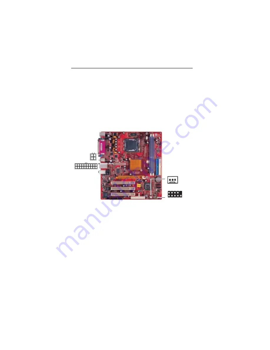
Connect the power connector from the power supply to the 

ATX1

connector on the motherboard. The 

PJ1

 is a +12V connector for

CPU Vcore power.

If there is a cooling fan installed in the system chassis, connect the
cable from the cooling fan to the 

SYSFAN1

 fan power connector

on the motherboard.

Connect the case switches and indicator LEDs to the 

SW1

header.

Install the Motherboard

Install the motherboard in a system chassis (case). The board is a
Micro ATX size motherboard. You can install this motherboard in
an ATX case. Make sure your case has an I/O cover plate
matching the ports on this motherboard.

Install the motherboard in a case. Follow the case manufacturer’s
instructions to use the hardware and internal mounting points on
the chassis.

ATX1

PJ1

1

SYSFAN1

SW1

1

Summary of Contents for P4VM800M7 Series

Page 1: ...ar purpose Further the manufacturer reserves the right to revise this publication and to make changes from time to time in the content hereof without obligation of the manufacturer to notify any perso...

Page 2: ...vices 20 Expansion Slots 23 Chapter 3 BIOS Setup Utility 25 Introduction 25 Running the Setup Utility 26 Standard CMOS Setup Page 27 Advanced Setup Page 28 Features Setup Page 30 Power Management Setu...

Page 3: ...ssible If you don t have a wrist strap discharge static electricity by touching the bare metal of the system chassis 3 Carefully hold this motherboard by its edges Do not touch those components unless...

Page 4: ...testing to verify its compatibility with Windows XP Please rest assured that our RD department has already tested and verified these drivers Just click the Continue Anyway button and go ahead the inst...

Page 5: ...providing higher bandwidth implementing Universal Serial Bus Specification Revision 2 0 and is compliant with UHCI 1 1 and EHCI 1 0 It supports 6 channel AC 97 Audio Codec and provides one IDE Ultra...

Page 6: ...s Highly Integrated Solutions for Performance PC Desktop Designs High performance Northbridge with 800 533 MHz Front Side Bus for Pentium 4 plus AGP 8x external bus Provide superior performance betwee...

Page 7: ...or DDR SDRAM memory modules Supports DDR 400 333 266 200 memory bus Maximum installed memory is 2GB Expansion Slots One 8x AGP slot Three 32 bit PCI slots for PCI 2 2 compliant bus interface One Commu...

Page 8: ...ts and connectors Two PS 2 ports for mouse and keyboard One serial port One parallel port One VGA port One LAN port optional Four back panel USB2 0 ports Audio jacks for microphone line in and line ou...

Page 9: ...rt PCI Bus Power Management Interface Specifica tion release 1 1 Legacy support for all downstream facing ports BIOS Firmware This motherboard uses AMI BIOS that enables users to configure many system...

Page 10: ...n cable The Software support CD Optional Accessories You can purchase the following optional accessories for this motherboard The Extended USB module The CNR v 90 56K Fax Modem card The Serial ATA cab...

Page 11: ...tly Install this motherboard in a system chassis case Connect any extension brackets or cables to headers connectors on the motherboard Install peripheral devices and make the appropriate connec tions...

Page 12: ...8 Motherboard User s Guide Motherboard Components DDR1 SYSFAN1 SW1 USB2 3 CPU_FAN DDR2 CNR1 ATX1 LGA775 Socket IDE1 SATA1 2 JP3 IR1 FDD1 IDE2 PCI1 3 AGP1 AUDIO1 PJ1 IO PORTS CD1 SPK1...

Page 13: ...Power connector IDE1 2 IDE connector SYSFAN1 Chasis cooling fan connector SATA1 2 Serial ATA connectors JP3 Clear CMOS jumper SW1 Front Panel Switch LED header FDD1 Floppy Disk Drive connector IR1 In...

Page 14: ...r parallel communications devices COM1 Use the COM port to connect serial devices such as mice or fax modems COM1 is identified by the system as COM1 VGA Use the VGA port to connect VGA devices LAN Po...

Page 15: ...bus frequency of the processor and the quantity of internal cache memory and external cache memory CPU Installation Procedure Follow these instructions to install the CPU A Unload the cap Use thumb fo...

Page 16: ...grease on top of the CPU F Fasten the cooling fan supporting base onto the CPU socket on the motherboard G Make sure the CPU fan is plugged to the CPU fan connector Please refer to the CPU cooling fa...

Page 17: ...y modules Double Data Rate SDRAM and maximum 2 0 GB installed memory DDR SDRAM is a type of SDRAM that supports data transfers on both edges of each clock cycle the rising and falling edges effectivel...

Page 18: ...socket 2 Align the memory module with the socket There is a notch on the DIMM socket that you can install the DIMM module in the correct direction Match the cutout on the DIMM module with the notch o...

Page 19: ...the contents of the CMOS memory You may need to clear the CMOS memory if the settings in the Setup Utility are incorrect and prevent your motherboard from operating To clear the CMOS memory disconnect...

Page 20: ...or on the motherboard Connect the case switches and indicator LEDs to the SW1 header Install the Motherboard Install the motherboard in a system chassis case The board is a MicroATX size motherboard Y...

Page 21: ...nts Pin Signal Pin Signal 1 HD_LED_P 2 FP PWR SLP 3 HD_LED_N 4 FP PWR SLP 5 RESET_SW_N 6 POWER_SW_P 7 RESET_SW_P 8 POWER_SW_N 9 RSVD_DNU 10 KEY Connecting Optional Devices Refer to the following for i...

Page 22: ...SB3 to connect the front mounted ports to the motherboard 1 Locate the USB2 USB3 header on the motherboard 2 Plug the bracket cable onto the USB2 USB3 header 3 Remove a slot cover from one of the expa...

Page 23: ...nd similarly equipped devices such as printers laptops Personal Digital Assistants PDAs and other computers 1 Locate the infrared port IR1 header on the motherboard 2 If you are adding an infrared por...

Page 24: ...20 Motherboard User s Guide Install Other Devices Install and connect any other devices in the system following the steps below SATA1 SATA2 IDE1 1 IDE2 1 FDD1 1...

Page 25: ...d one of the drives as Slave The documentation of the IDE device will tell you how to configure the device as a Master or Slave device The Master device connects to the end of the cable Install the de...

Page 26: ...asier PC assembly It eliminates limitations of the current Parallel ATA interface but maintains register compatibility and software compatibility with Parallel ATA Analog Audio Input Header If you hav...

Page 27: ...23 Chapter2 Motherboard Installation Expansion Slots This motherboard has one AGP one CNR and three 32 bit PCI slots AGP1 PCI1 PCI2 CNR1 PCI3...

Page 28: ...the slot Ensure the edge connector is correctly seated in the slot 4 Secure the metal bracket of the card to the system chassis with a screw 8x 4x AGP Slot You can install a graphics adapter that supp...

Page 29: ...Setup Utility configuration is incorrect it may cause the system to malfunction It can even stop your computer booting properly If it happens you can use the clear CMOS jumper to clear the CMOS memory...

Page 30: ...and press and keys to cycle through alternative values of that item The other options on the main menu page lead to dialog boxes requiring your answer OK or Cancel by selecting OK or Cancel If you ha...

Page 31: ...y If you have a CD ROM drive select the setting CDROM If you have an ATAPI device with removable media e g a ZIP drive or an LS 120 select Floptical Floppy A Floppy B These items set up size and capac...

Page 32: ...an operating system from the first two locations BootUp Num Lock This item determines if the Num Lock key is active or inactive at system start up time CMOS SETUP UTILITY Copyright C 1985 2004 America...

Page 33: ...ur P4 CPU is HT CPU BIOS will show this item You can set Disabled or Enabled to control HT CPU support in O S Set Enabled to test HT CPU function Auto detect DIMM PCI Clock When this item is enabled B...

Page 34: ...ess Parallel Port Mode ECP Use this item to select the parallel port mode You can select Normal Standard Parallel Port ECP Extended Capabilities CMOS SETUP UTILITY Copyright C 1985 2004 American Megat...

Page 35: ...her or both of the onboard Primary and Secondary IDE channels OnBoard SATA IDE Use this item to enable or disable the onboard IDE channel Audio Device Use this item to enable or disable the onboard au...

Page 36: ...time selected passes without any system activity the computer will enter power saving Suspend mode Power Management Setup Page This page sets some parameters for system power management operation CMO...

Page 37: ...in order to use this feature LAN Ring Power On The system can be turned off with a software command If you enable this item the system can automatically resume if there is an incoming call on the Mode...

Page 38: ...n of the main memory for the onbaord VGA display application with these options of 64 32 16 8 MB Allocate IRQ to PCI VGA If this item is enabled an IRQ will be assigned to the PCI VGA graphics system...

Page 39: ...ion and press Enter to access the sub menu You can use the sub menu to change the supervisor pass word Password Check This item enables users to choose the time when the system will perform password c...

Page 40: ...cides the CPU over clocking function installed in your system If the over clocking fails please turn off the system power And then hold the PageUp key similar to the Clear CMOS function and turn on th...

Page 41: ...x appears If you select OK and then press Enter the Setup Utility loads a set of fail safe default values These default values are not very demanding and they should allow your system to function with...

Page 42: ...eturn to the main menu Discard Changes and Exit Highlight this item and press Enter to discard any changes that you have made in the Setup Utility and exit the Setup Utility When the Discard Changes a...

Page 43: ...EADME file located in the same directory as the software To run the support CD simply insert the CD into your CD ROM drive An Auto Setup screen automatically pops out and then you can go on the auto i...

Page 44: ...p button runs the software auto installing program as explained in next section The Browse CD button is a standard Windows command that you can check the contents of the disc with the Windows 98 file...

Page 45: ...n 2 Select the items that you want to setup by clicking on it the default options are recommended Click the Next button to proceed 3 The support software will automatically install Once any of the ins...

Page 46: ...of the screen 2 Find out your mainboard model name and click on it to obtain its correct driver directory 3 Install each software in accordance with the corresponding driver path Bundled Software Inst...

Page 47: ...e you are in Windows Task Manager please push down ctrl Alt Del keys A dual CPU appears in the CPU Usage History Device Manager under WinXP Note Hyper Threading Function only works under WINXP Operati...

Reviews: