Mercury KVM400M-L User Manual Download Page 21


Floppy Disk Drive 

The mainboard ships with a floppy disk drive cable that can 
support one or two drives. Drives can be 3.5” or 5.25” wide, with 
capacities of 360K, 720K, 1.2MB, 1.44MB, or 2.88MB.  
Install your drives and connect power from the system power 
supply. Use the cable provided to connect the drives to the floppy 
disk drive connector 

FDC1

.  


IDE Devices 

IDE devices include hard disk drives, high-density diskette drives, 
and CD-ROM or DVD-ROM drives, among others. 
The mainboard ships with an IDE cable that can support one or two 
IDE devices. If you connect two devices to a single cable, you 
must configure one of the drives as Master and one of the drives as 
Slave. The documentation of the IDE device will tell you how to 
configure the device as a Master or Slave device. The Master 
device connects to the end of the cable. 
Install the device(s) and connect power from the system power 
supply. Use the cable provided to connect the device(s) to the 
Primary IDE channel connector 

IDE1

 on the mainboard. 

If you want to install more IDE devices, you can purchase a second 
IDE cable and connect one or two devices to the Secondary IDE 
channel connector 

IDE2

 on the mainboard. If you have two 

devices on the cable, one must be Master and one must be Slave. 
 

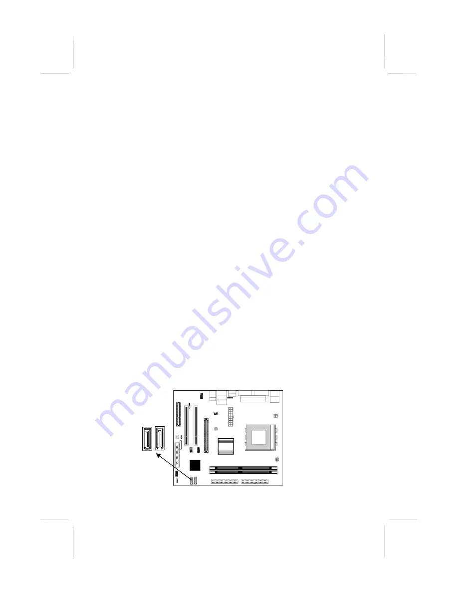
Serial ATA Connector: J4 & J5 (only for SB VT8237) 

Your mainboard has two SATA connectors to support the Serial 
ATA (Advanced Technology Attachment) standard interface for 
the IDE hard drives.  


J5 J4


17

Summary of Contents for KVM400M-L

Page 1: ...d to make changes from time to time in the content hereof without obligation of the manufacturer to notify any person of such revision or changes Trademarks IBM VGA and PS 2 are registered trademarks...

Page 2: ...ng Optional Devices 14 Install Other Devices 16 Expansion Slots 19 Chapter 3 BIOS Setup Utility 20 Introduction 20 Running the Setup Utility 21 Standard CMOS Setup Page 22 Advanced Setup Page 23 Power...

Page 3: ...y its compatibility with Windows XP Please rest assured that our RD department has already tested and verified these drivers Just click the Continue Anyway button and go ahead the installation 2 USB 2...

Page 4: ......

Page 5: ...e CNR Communications and Networking Riser slot to support Audio and Modem application two PCI slots and the built in 10BaseT 100BaseTX Network Interface optional There is a full set of I O ports inclu...

Page 6: ...ll be two extra USB connectors USB2 USB3 and two Serial ATA connectors J4 J5 when SB is VT8237 only one extra USB connector USB2 when SB is VT8235CE Memory Support Two 184 pin DIMM sockets for DDR mem...

Page 7: ...mainboard has a full set of I O ports and connectors Two PS 2 ports for mouse and keyboard One serial port One parallel port One VGA port Eight USB2 0 ports with SB VT8237 or six ports with SB VT8235C...

Page 8: ...ntroller cores for full low speed signaling and one EHCI Host Controller core for high speed signaling Root hub consists 4 downstream facing ports with integrated physical layer transceivers shared by...

Page 9: ...drive ribbon cable Software support CD Optional Accessories You can purchase the following optional accessories for this mainboard Extended USB module CNR v 90 56K Fax Modem card Card Reader You can...

Page 10: ...don t have a wrist strap discharge static electricity by touching the bare metal of the system chassis 3 Carefully hold this mainboard by its edges Do not touch those components unless it is absolutel...

Page 11: ...ainboard in a system chassis case Connect any extension brackets or cables to connectors on the mainboard Install any peripheral devices and make the appropriate connections to connectors on the mainb...

Page 12: ...am underneath Note 1 Any jumpers on your mainboard not appearing in the illustration above are for testing only Note 2 There will be two extra USB connectors USB2 USB3 and two Serial ATA connectors J4...

Page 13: ...OM port to connect serial devices such as mice or fax modems COM1 is identified by the system as COM1 3 LAN Port optional Connect an RJ 45 jack to the LAN port to connect your computer to the Network...

Page 14: ...462 Pin 1 1 CPU_FAN1 1 Unhook the locking lever of the CPU socket Pull the locking lever away from the socket and raising it to the upright position 2 Match the pin1 corner marked as the beveled edge...

Page 15: ...y work with 100MHz 133MHz or 166MHz 200MHz KM400A memory bus DDR SDRAM provides 1 6 GB s or 2 1 GB s data transfer rate depending on whether the bus is 100MHz 133MHz or 166MHz 200MHz KM400A DDR SDRAM...

Page 16: ...pins is SHORT removing it from these pins OPEN JP3 1 1 CLEAR_CMOS1 Jumper CLEAR_CMOS1 Clear CMOS Memory Use this jumper to clear the contents of the CMOS memory You may need to clear the CMOS memory...

Page 17: ...that matches the ports on this mainboard Install the mainboard in a case Follow the instructions of the case manufacturer to use the hardware and internal mounting points on the chassis 1 J3 SYS_ FAN...

Page 18: ...e cable from the PC speaker to the SPK1 connector on the mainboard Pin Signal Pin Signal 1 SPKR 2 NC 3 GND 4 5V AUDIO1 Front Panel Audio Connector This header allows the user to install auxiliary fron...

Page 19: ...ctor 3 Remove a slot cover from one of the expansion slots on the system chassis Install an extension bracket in the opening Secure the extension bracket to the chassis with a screw Note When the SB V...

Page 20: ...t allows the wireless exchange of information between your computer and similarly equipped devices such as printers laptops Personal Digital Assistants PDAs and other computers Pin Signal Pin Signal 1...

Page 21: ...ves as Master and one of the drives as Slave The documentation of the IDE device will tell you how to configure the device as a Master or Slave device The Master device connects to the end of the cabl...

Page 22: ...mpatibility with Parallel ATA Internal Sound Connections If you have installed a CD ROM drive or DVD ROM drive you can connect the drive audio cable to the onboard sound system 1 CD1 When you first st...

Page 23: ...Peripheral Components Interconnect Slots You can install the 32 bit PCI interface expansion cards in the slots AGP Accelerated Graphics Port Slot You can install a graphics adapter supporting 8xAGP sp...

Page 24: ...oordination between system components If the Setup Utility configuration is incorrect it may cause the system to malfunction It can even stop your computer from booting properly If this happens you ca...

Page 25: ...type etc You can use the cursor arrow keys to highlight any of the options on the main menu page Press Enter to select the highlighted option To leave the setup utility press the Escape key To cycle...

Page 26: ...stalled Month Jan Dec ESC Exit Day 01 31 Select Item Year 1901 2099 PU PD Modify Shift F2 Color F3 Detect All HDD Date Time Use these items to set the system date and time Pri Master Pri Slave Sec Mas...

Page 27: ...RAM CAS Latency 2 5 SDRAM Bank Interleave 2 Way Auto Detect DIMM PCI Clk Enabled Spread Spectrum Disabled ESC Quit Select Item F1 Help PU PD Modify F5 Old Values Shift F2 Color F6 Load BIOS Defaults F...

Page 28: ...is required to enter the Setup Utility Setup or required both at start up and to enter the Setup Utility Always Boot to OS 2 64MB Enable this item if you are booting the OS 2 operating system and you...

Page 29: ...free DIMM PCI slots Spread Spectrum If you enable spread spectrum it can significantly reduce the EMI Electro Magnetic Interference generated by the system Power Management Setup Page This page sets...

Page 30: ...utomatically resume at a fixed time based on the system s RTC realtime clock Use the items below this one to set the date and time of the wake up alarm You must use an ATX power supply in order to use...

Page 31: ...tup Defaults Share Memory Size This item lets you allocate a portion of the main memory for the onboard VGA display application with 8 16 32MB options Primary Graphics Adapter This item indicates if t...

Page 32: ...g and your system might not function properly if you are using slower memory chips or other low performance components Features Setup Page This page sets some of the parameters for peripheral devices...

Page 33: ...s item to assign either IRQ 5 or 7 to the parallel port Parallel Port DMA Use this item to assign a DMA channel to the parallel port The options are 0 1 and 3 Onboard PCI IDE This item enables or disa...

Page 34: ...uit Select Item F1 Help PU PD Modify F5 Old Values Shift F2 Color F6 Load Optimal values F7 Load Best performance values CPU Over Clocking Func This item enables or disables the CPU over clocking func...

Page 35: ...PU System Temperature These items display CPU and system temperature measurement FANs Voltage Measurements These items indicate cooling fan speeds in RPM and the various system voltage measurements Ch...

Page 36: ...type in the new password or just press Enter to disable password protection Exit Highlight this item and press Enter to save the changes that you have made in the Setup Utility configuration and exit...

Page 37: ...n the same directory as the software To run the support CD simply insert the CD into your CD ROM drive An Auto Setup screen automatically pops out and then you can go on the auto installing or manual...

Page 38: ...he software auto installing program as explained in next section The Browse CD button is a standard Windows command that you can check the contents of the disc with the Windows 98 file browsing interf...

Page 39: ...he items that you want to setup by clicking on it the default options are recommended Click the Next button to proceed 3 The support software will automatically install Once any of the installation pr...

Page 40: ...Find out your mainboard model name and click on it to obtain its correct driver directory 3 Install each software in accordance with the corresponding driver path Bundled Software Installation All bun...

Reviews: