Mercury 75 OptiMax Installation Manual Download Page 3

75/90/115  OPTIMAX

Page 3 of 18

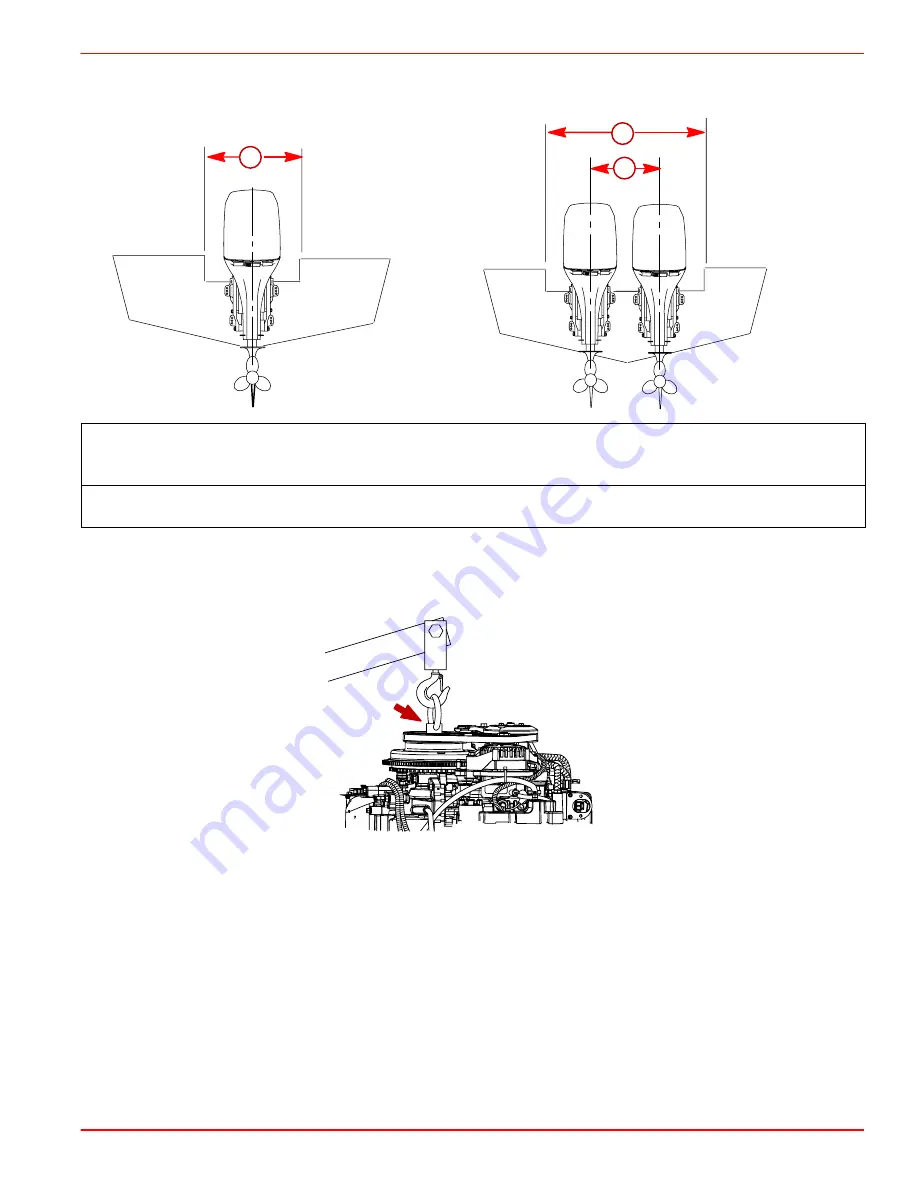
Installation Specifications

a

b

a

a – Transom Opening – Minimum 
Single Engine (Remote) – 33-3/8 in. (848 mm)
Dual Engines – 59-3/4 in. (1518 mm)

b – Engine Center Line For Dual Engine 
26 in. (660mm) Minimum

Lifting Outboard

Use Flywheel Puller/Lifting Eye (91-83164M).

Summary of Contents for 75 OptiMax

Page 1: ...he operation procedures in the Operation and Maintenance Manual Important Information Before Starting Engine Before starting engine for the first time prime the oil injection pump Procedure on page 16...

Page 2: ...must be equipped with a start in gear protec tion device This prevents the engine from starting in gear WARNING Avoid serious injury or death from a sudden unexpected acceleration when starting your...

Page 3: ...ation Specifications a b a a Transom Opening Minimum Single Engine Remote 33 3 8 in 848 mm Dual Engines 59 3 4 in 1518 mm b Engine Center Line For Dual Engine 26 in 660mm Minimum Lifting Outboard Use...

Page 4: ...MAX Page 4 of 18 Steering Cable STARBOARD SIDE ROUTED CABLE 1 Lubricate O ring seal and entire cable end 95 95 2 4 C With Teflon 92 825407A12 2 Insert steering cable into tilt tube 3 Torque nut to 35...

Page 5: ...steering link rod that connects the steering cable to the engine must be fastened using special bolt a Part Number 10 848838 and self locking nuts b c Part Number 11 34863 These locknuts must never b...

Page 6: ...be preferred to determine outboard mounting height dimension if maximum speed is the only objective This line may be preferred to determine outboard mounting height dimension for dual outboard install...

Page 7: ...and drill four 17 32 in 13 5mm mounting holes 3 Refer to Determining Recommended Outboard Motor Mounting Height preceding and install outboard to the nearest recommended mounting height 4 Fasten outb...

Page 8: ...ws 2 b Cover INSTALLATION IMPORTANT Sufficient slack must exist in engine wiring harness battery cables fuel hose and routed between clamp and engine attachment point to relieve stress and prevent hos...

Page 9: ...the harness connection and retainer into the cable holder lo cated in the bottom cowl has shown GRN WHT BLU WHT BRN WHT TAN BLU WHT GRN WHT a TAN BRN WHT b c d e a Power Trim Connections b Wire Conne...

Page 10: ...Sleeve Positive b Black Sleeve Negative c Starting Battery DUAL OUTBOARDS Connect a common ground cable wire size same as engine battery cables between nega tive terminals on starting batteries d d G...

Page 11: ...ickup for each engine FUEL HOSE CONNECTION Fasten remote fuel hose to fitting with hose clamp Water Pressure Tubing Connection Models without SmartCraft Water PSI Gauge Make the water pressure gauge h...

Page 12: ...Install the shift cable to the engine first The shift cable is the first cable to move when the remote control handle is moved out of neutral 1 Position remote control into neutral N 2 Shift outboard...

Page 13: ...Shift remote control into forward The propeller shaft should be locked in gear If not adjust the barrel closer to the cable end b Shift remote control into neutral The propeller shaft should turn free...

Page 14: ...nstall throttle cable to the throttle arm with washer and locknut 3 Adjust the cable barrel so that the installed throttle cable will hold the throttle arm against the idle stop 4 Place cable barrel i...

Page 15: ...in for three seconds Continue this procedure until the fuel line primer bulb stays firm Filling The Oil Injection Tank NOTE The oil tank capacity is 5 qt 4 72 liters 1 Open the cowl cap Turn the oil f...

Page 16: ...el Other wise the fuel pumps will run without fuel during the priming process Prime the oil injection pump as follows 1 Fill the engine fuel system with fuel Connect fuel hose and squeeze primer bulb...

Page 17: ...always shift outboard to neutral position and remove spark plug leads when you are servicing the propeller IMPORTANT Propellers used on this product require the Mercury Marine Flo Torq lll type hub 8...

Page 18: ...bow down planing condition called plowing Plowing can cause bow steering or over steering and inefficiently consumes horsepower In this condition if attempting a turn or encountering a diagonal moder...

Reviews: