200/225/250/275 VERADO 4-STROKE
90-10238051
Page 45 / 51
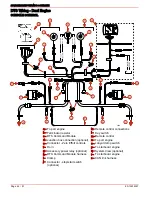
System Wiring Installation Checklist
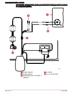
DATA CABLE
Verify the data harness is not routed near sharp edges, hot surfaces or moving parts.
Verify data harness is not routed near ignition components (coils, spark plug leads,
and spark plugs), high power VHF coax or radios.
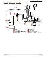
JUNCTION BOX (IF EQUIPPED)
Verify the data harness is not routed near sharp edges, hot surfaces or moving parts.
Ensure the harness connections are fastened within 25.4 cm (10 in.).
Verify that all unused receptacles are covered with a weather cap.
NON-MERCURY MARINE SUPPLIED IGNITION KEY SWITCH
If a non-Mercury Marine ignition key is used, verify that it passes the ingress protection
testing per IEC IP66 specification minimum. Ignition switches must pass this
specification.
ELECTRONIC REMOTE CONTROL
Ensure Electronic Remote Control (ERC) connections are completed following ERC
installation instructions prior to engine operation.
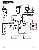
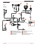
DTS COMMAND MODULE HARNESS
Verify that all connectors are properly inserted and locked in their receptacle (remote
control, key switch, command module, lanyard stop switch and junction box, if
equipped).
Verify that while moving the remote control handle (full forward and full reverse) the
harness has unobstructed movement (moves freely).
Verify that the lanyard stop switch is wired into the system correctly.
Verify that the harness is fastened along the routing path.
Verify that all unused connectors have weather caps to prevent corrosion.
BATTERY
Verify that wing nuts have been replaced with hex nuts, provided.
Verify that all engine battery cables are connected to the correct terminals.
Verify that the DTS power harness leads are connected to the starting battery and
secured with locknuts.
Ensure the 5 Amp fuse for the DTS power harness is accessible.
LANYARD STOP SWITCH
Verify that the switch is installed.
Verify that the switch is connected to the DTS command module harness.
Propeller Installation
!
WARNING
When installing or removing propeller, ensure the remote control is in neutral position
and the key switch is "OFF". Place a block of wood between the anti-cavitation plate
and propeller to prevent accidental starting and to protect hands from propeller blades
while removing or installing nut.
1. To aid in future removal of the propeller, liberally coat the propeller shaft splines with
one of the following Mercury/Quicksilver products:

