background image


EXi-F 

 positive pressure smoke control system 


„MERCOR” S.A. – 

Specifications are subject to change without notice. Version DTR_EXIF_EN_20220516


Page 

20

 / 28


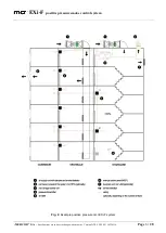
Fig. 16.


Example mcr EXi-F air intake unit in roof-mounted version with two intake vents 


 (1 - fan, 2 – intake vent, 3 - vibration damper, 3 - flexible connector,  

4 – dampers with actuators in two intake vent configuration, 5 - duct smoke detectors in external version) 


4.3.2.


Duct smoke detector UG-3-A4

 _____________________________________________ 


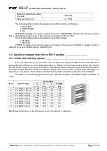
If  the  air  inlet  is  not  at  the  roof  level,  in  the  inlet  duct  or  directly  near  the  air  supply  ducts,  a 

smoke  detector  for  automatic  deactivation  of  the  pressure  differential  system  should  be  provided  in 
case when large volumes of smoke are present in the supplied air. 


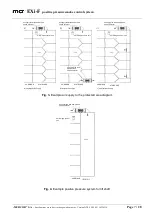
If the air inlets are at the roof level, two air inlets are required (two intake vents configuration). 

Each inlet must be protected by an independent damper system with a duct smoke detector installed 
upstream. 


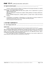
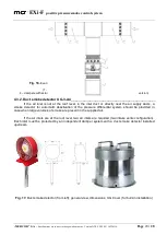
Fig. 17.

 Duct smoke detector (from left): general view, dimensions, UG Cover (for built-in installation)


Summary of Contents for EXi-F

Page 1: ...2 80 408 Gdańsk phone 0 58 341 42 45 tel fax 0 58 341 39 85 OPERATION AND MAINTENANCE MANUAL mcr EXi F pressure differential system kit for smoke and heat control systems No EXi F 005 2022 FIRE VENTILATION SYSTEM DEPARTMENT ...

Page 2: ...DIFFERENTIAL PRESSURE TRANSMITTER 17 4 2 1 MCR ICS DIGITAL DIFFERENTIAL PRESSURE TRANSMITTER 17 4 3 AUXILIARY COMPONENTS OF MCR EXI F SYSTEM 19 4 3 1 INTAKE VENT SWITCHING SYSTEM 19 4 3 2 DUCT SMOKE DETECTOR UG 3 A4 20 4 3 3 MANUAL CONTROL PANEL MCP 21 5 WIRING SYSTEM 22 5 1 MCR OMEGA CONTROL SUPPLY UNIT 22 5 2 MCR EXI F AIR SUPPLY UNITS 23 5 3 MCR ICS PRESSURE TRANSMITTERS 24 5 3 1 MCR ICS DIGITA...

Page 3: ...anual applies to mcr EXi F positive pressure smoke control system for escape routes The system includes a group of products selected and configured to establish a protected area with a specific positive pressure in accordance with the design requirements The system is manufactured by MERCOR SA ul Grzegorza z Sanoka 2 80 408 Gdańsk mcr EXi F system components 1 mcr Omega control unit CU Omega 2 mcr...

Page 4: ...ss mcr EXi F system can be used in staircases with protected lobbies and is compatible with systems including at least one pressure transmitter per protected area mcr EXi F system consists of a configured set of devices preventing smoke ingress to the protected area by increasing pressure Fig 1 Example mcr EXi F system diagram Depending on the demand air can be supplied to the protected area using...

Page 5: ...d by a variable air volume supplied to the protected area by the air supply unit s Provided that the door to the protected area are closed the main fan of the air supply unit maintains a stable positive pressure The actual pressure in the protected area is measured and controlled by mcr ICS The positive pressure in the staircase 20 80 Pa guarantees that the force required to open the exit door doe...

Page 6: ...EXi F positive pressure smoke control system MERCOR S A Specifications are subject to change without notice Version DTR_EXIF_EN_20220516 Page 6 28 Fig 2 Example positive pressure mcr EXi F system ...

Page 7: ...ply fan with damper and smoke detector air supply fan with damper and smoke detector air supply fan with damper and smoke detector mcr Omega control unit mcr Omega control unit mcr Omega control unit air supply fan with damper and smoke detector CORRIDOR STAIRCASE STAIRCASE CORRIDOR CORRIDOR STAIRCASE a single point air supply b two point air supply c multi point air supply air supply fan with dam...

Page 8: ...hnical conditions for buildings and their location Dz U No 75 of 2002 item 690 as amended Technical Approval ITB KOT 2021 1788 4 SYSTEM COMPONENTS __________________________________________ 4 1 mcr Omega control unit ___________________________________________________ Applications _______________________________________________________ mcr EXi F pressure differential system kit uses mcr Omega cont...

Page 9: ... system MERCOR S A Specifications are subject to change without notice Version DTR_EXIF_EN_20220516 Page 9 28 Fig 5 Example mcr EXi F system control configuration diagram Operation__________________________________________________________ ...

Page 10: ...red by an incoming panel for fire protection equipment which is not being disconnected with a fire switch or is equipped with an automatic reserve power switch ARPS in buildings where no incoming panel for fire protection equipment is available in the main switchboard mcr Omega control unit is delivered in powder coated on stainless steel enclosure with front door and IP55 protection rating extern...

Page 11: ...t precipitation and solar radiation is required in external use power supply and control of smoke control devices and fire divisions which require auxiliary power supply as per relevant regulations Control unit components depending on the system size automatics and control block with advanced microprocessor monitoring and control modules mcr MMS and intelligent mcr ICR positive pressure regulator ...

Page 12: ...no alarm If the contact is opened the controller reads the resistor resistance and executes a program stored in its memory If the resistance at the controller input increases to infinity the unit treats it as a failure indicates the status with controller lights and transmits a signal After installing and checking the correct operation of all system components the system starts the adaptation proc...

Page 13: ...ith optional accessories mcr EXI F air supply unit a multi blade damper with BLF BF BFL BFN BLE BE NMQ LMQ SMQ NF SF or MF MLF series actuator b duct smoke detector optional c mcr LAM exhaust vent vertical installation of fans in box housing converging pipe with flange beveled duct with grille mcr EXi F air supply units include mcr Monsun E1 series axial fans in a box type housing Air supply fans ...

Page 14: ...nditions with mcr LAM louver vents Fig 13 The declared properties and features of LAM vent e g snow load SL 1300 wind load WL 1500 guarantee operation in extreme weather conditions For vertical installation indoors the unit is mounted on the supporting structure and connected to the air supply system in accordance with the design requirements mcr EXI F air supply units include multi blade dampers ...

Page 15: ...0 238 5 mcr EXi F 80 1S 1000 1000 900 900 810 130 200 115 640 60 156 6 mcr EXi F 71 1S 1000 1000 900 900 810 130 200 115 640 60 156 7 mcr EXi F 71 2S 1000 1000 900 900 810 130 200 115 640 60 156 8 mcr EXi F 63 1S 825 825 700 700 710 130 200 115 525 60 101 Item System type A mm B mm C mm D mm d mm 1 mcr EXi F 100 1S 1200 1150 860 884 13 2 mcr EXi F 100 2S 1200 1150 860 884 13 3 mcr EXi F 90 1S 1200...

Page 16: ...200 1200 1300 1300 300 750 320 326 5 mcr EXi F 80 1S H 1000 1000 1100 1100 300 650 320 228 6 mcr EXi F 71 1S H 1000 1000 1100 1100 300 650 320 228 7 mcr EXi F 71 2S H 1000 1000 1100 1100 300 650 320 228 8 mcr EXi F 63 1S H 825 825 945 945 300 550 320 157 Fig 10 Dimensions and weights of mcr EXi F air supply kit with fan in box housing Fig 11 Example mcr EXi F air supply unit in wall mounted versio...

Page 17: ... air supply unit 1 fan in box housing 2 ventilation duct 3 damper 4 duct smoke detector 5 flexible connector 6 fan inlet protection 7 junction box 9 noise suppresor 4 2 Differential pressure transmitter ____________________________________________ 4 2 1 mcr ICS digital differential pressure transmitter ______________________________ The device measures differential pressure in a protected area at ...

Page 18: ...end periodical status information to the regulator to ensure continuous monitoring of the system status and detection of the following failures line discontinuity mcr ICS digital pressure transmitter removed or faulty alarm input discontinuity for mcr ICS digital pressure transmitter failure for mcr ICS The pressure source is connected via a flexible 8 mm dia pressure line 5 m pressure line includ...

Page 19: ..._________________ If the air inlets are at the roof level two air inlets are required distant from each other and facing different direction to avoid leeward position in relation to the smoke source Each inlet should provide full air supply required by the system All inlets should be protected by an independent system of smoke control dampers when one damper closes due to the smoke another inlet w...

Page 20: ...r UG 3 A4 _____________________________________________ If the air inlet is not at the roof level in the inlet duct or directly near the air supply ducts a smoke detector for automatic deactivation of the pressure differential system should be provided in case when large volumes of smoke are present in the supplied air If the air inlets are at the roof level two air inlets are required two intake ...

Page 21: ... fire fighting operations The panel should be located near the fire exits and easily accessible to the rescuers The panel indicates unit operation status power supply green light ON indicates correct system operation failure yellow light ON indicates system failure alarm red light ON indicates alarm lock blinking yellow light indicates manual lock air inlet fan operation green light ON indicates a...

Page 22: ...ff dampers power supply and operation of the duct smoke detector power supply control and monitoring of dampers used in differential pressure system The control unit is supplied with 3 x 400 V The control supply unit is powered by an incoming panel for fire protection equipment which is not disconnected with a fire switch or is equipped with an automatic reserve power switch ARPS in buildings wher...

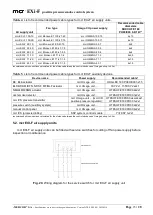
Page 23: ...d Omega unit up to 50 m Table 5 List of recommended power cable types for mcr EXi F auxiliary devices recommended cross sections calculated for the distance between the control devices and Omega unit up to 50 m 5 2 mcr EXI F air supply units mcr EXI F air supply units can be fitted with service switches for cutting off fan power supply before inspection or maintenance Fig 20 Wiring diagram for the...

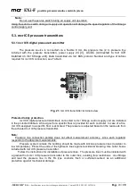
Page 24: ...itters connected to mcr Omega control supply unit are installed in the protected lobbies A fire signal for a specific floor is provided for each controller In case of a fire mcr ICS assigned to a specific floor is activated The pressure is adjusted based on the read outs from the activated mcr ICS pressure transmitter Note Pressure line connection polarity does not affect measurement accuracy sinc...

Page 25: ...sure line length should not exceed 12 m Additional set of pressure lines include 4 fittings 2 elbows and 2 straight connectors Fig 23 Additional pressure line set with accessories Pressure system outside the building should be made with silicone pressure lines resistant to low temperature Protect the ends of the hydraulic lines against accidental blocking Use back boxes with pre drilled holes in t...

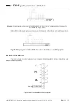
Page 26: ... mcr EXI F air supply units Belimo BE actuators no spring return are used in dampers in the intake vent switching system Fig 25 Wiring diagram for Belimo BE BLE actuator in two intake vent switching system 5 5 Duct smoke detector The duct smoke detector features relay outputs indicating alarm smoke detecting and technical alarm service Fig 26 Duct smoke detector wiring diagram Power supply Alarm o...

Page 27: ... and post warranty period Inspections and maintenance must be carried out by the device manufacturer or a service centre authorized by MERCOR S A The service inspections of fire protection devices are required by the 3 sec 3 of the Regulation of the Minister of Interior and Administration of 7 June 2010 on fire protection of buildings other construction facilities and sites Journal of Laws Dz U 20...

Page 28: ...ssive external factors in particular chemical and biological factors arising from the production processes and activities on site or in the vicinity of the device natural wear and tear e g gaskets unless an inherent defect was identified damage due to the incorrect transport unloading and storage damage due to the failure to follow the installation instruction in the Operation and Maintenance Manu...

Reviews: