


List of Illustrations
_____________________________________________________________________
Status September 2003 (EvoBus-Service / AFT)
Page: 7 of 83
Overall system of natural gas engine........................................................................................................ 10
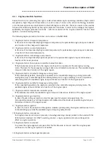
Basic EGM functions ................................................................................................................................ 12
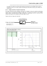
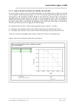
Engine protection: charge-air temperature............................................................................................... 15
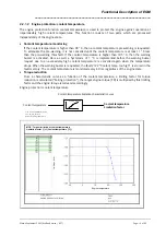
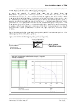
Engine protection: coolant temperature................................................................................................... 16
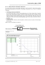
Engine protection: turbocharger overpressure ......................................................................................... 17
Engine protection: boost-pressure substitute value formation ................................................................. 18
Engine protection: Crankshaft emergency-running mode (dual ignition)................................................... 19
Engine protection: Camshaft emergency-running mode (failure of crankshaft signal) .............................. 20
Engine protection: lambda lean-controller probe...................................................................................... 21
Engine protection: gas injection............................................................................................................... 22
Engine protection: ignition ....................................................................................................................... 23
Engine protection: oil pressure pre-warning threshold ............................................................................. 24
Engine protection: oil-pressure warning threshold ................................................................................... 25
Idling control: target idling speed............................................................................................................. 27
Throttle valve control: TV = f(throttle valve position) ................................................................................ 29
Schematic diagram of wastegate actuation.............................................................................................. 31
Switch-on conditions for boost-pressure control...................................................................................... 32
Switch-on threshold for boost-pressure control ....................................................................................... 33
Switch-off threshold for boost-pressure control ....................................................................................... 33
Overview: gas mass calculation in normal operation................................................................................ 36
Release of gas injection and actuation of gas cut-off valve ...................................................................... 39
Function overview of firing angle calculation............................................................................................ 41
Block diagram for electrical description: .................................................................................................. 42
Actuation phases and current curve of gas injectors................................................................................ 51
Principle of ignition actuation:.................................................................................................................. 53
Determining the target engine torque ...................................................................................................... 55
Characteristic curve: Exhaust-gas temperature sensor ............................................................................ 57
Characteristic curve: Coolant temperature sensor................................................................................... 58
Characteristic curve: Gas temperature sensor ......................................................................................... 59
Characteristic curve: Gas pressure sensor............................................................................................... 60
Characteristic curve: Oil temperature sensor........................................................................................... 61
Characteristic curve: Charge-air temperature sensor............................................................................... 62
Characteristic curve: Boost pressure sensor............................................................................................ 63
Characteristic curve: Atmospheric pressure sensor ................................................................................. 64
Characteristic curve: Oil pressure sensor................................................................................................. 65
Performance graph for O 447 hLAG, 240 kW........................................................................................... 78
Performance graph for M 447 hLAG, 185 kW .......................................................................................... 78
Drawing: pulse width modulated signal .................................................................................................... 80
Overview of bus systems (EvoBus) ........................................................................................................... 81