background image

  Hardware Installation

Memotec Inc.

4-19

• Available console speeds are 1200, 2400, 4800, 9600, 19200, 28800, 38400, 

57600 and 115200 bps. 

The equipment you connect to the console port must 

operate at one of these speeds.

4.9.2

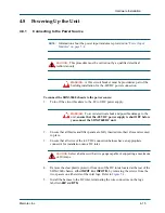
Activating the Console Connection

To activate the console connection:

1.

Ensure that all SDM-9606 blades have successfully powered up with no system status 
errors (see 

“System Status on Power-up” on page 4-16

).

2.

Power the console terminal on or start your console terminal emulation program.

Take note of:

“Important Console and Modem Settings for Startup” on page 4-18

“Notice Concerning HyperTerminal Connections” on page 8-1

.

3.

When you see the prompt 

Type <ENTER> to connect

, press the 

<Enter>

 key on the 

console terminal keyboard several times, until the NetPerformer responds with a 
prompt for the user login.

4.

Enter the administrator login: 

ADMIN

.

This is the default login. Additional user logins can be defined. For details, refer to 
the chapter 

Controlling Access to the NetPerformer

 in the 

Quick 

Configuration

 fascicle of the 

NetPerformer System Reference

.

5.

Enter the password for this login. The default password for the administrator login is


SETUP

.

When the password is entered correctly, the SDM-9606 blade sends the product 
banner to the console screen, as in this example:

LOGIN:

ADMIN

PASSWORD:

*****

ACCEPTED

SDM-9606 vx.x.x Memotec Technologies, Inc. (c) 2007

DSP QCxxx.BIZ code version: x.x.x

Console connected through TELNET

Voice transport method:  PowerCell

Display commands, type HE

B3046082>

6.

Enter the Display Alarms (

DA

) command at the NetPerformer console command line 

to verify that your unit is problem free. In particular, look for any alarm messages that 
indicate 

Call Technical Support

.

Summary of Contents for NetPerformer SDM-9600

Page 1: ...NetPerformer SDM 9600 with SDM 9606 Blades Hardware Installation Guide...

Page 2: ...incorporated in new editions of these documents Memotec may make improvements or changes in the products or programs described within the documents at any time without notice Mention of products or se...

Page 3: ...uct Work Order Number 1 8 1 5 4 Checking the Contents of Your Product Package 1 9 1 5 5 Returning an SDM 9600 Chassis or SDM 9606 Blade 1 10 1 6 Sales Contacts 1 11 Chapter 2 Compliance Information 2...

Page 4: ...on of DSP Socket on the SDM 9606 Blade 4 4 4 3 2 Installation Procedure 4 5 4 4 Hardware Strapping for E1 Ports 4 8 4 4 1 Strapping for E1 75 Operation 4 8 4 5 Installing a Blade 4 9 4 6 Removing a Bl...

Page 5: ...5 6 3 LAN Cables 5 9 5 6 4 RJ 45 Connector for Ethernet LAN Port 5 10 5 7 DSP Modules 5 11 5 7 1 High density DSP Modules 5 11 5 8 Console Port 5 13 5 8 1 Port 5 13 5 8 2 Console Cable 5 13 5 8 3 RJ 4...

Page 6: ...Memotec Inc 7 4 Network Management and Security 7 5 Index 7...

Page 7: ...stalling an SDM 9606Blade in the SDM 9600 Chassis 4 9 Blade Handle Operation 4 12 Rear View of the SDM 9600 Chassis with Filler Panels 4 14 Accessing the Air Filter Tray 4 23 Air Filter and Outer Gril...

Page 8: ...Memotec Inc...

Page 9: ...assis 5 2 Feature items for the SDM 9606 blade 5 2 Feature items for optional hardware 5 2 SDM 9606 ports 5 7 ST LED states 5 8 ALM LED states 5 8 RJ 45 pinout for Ethernet LAN port 5 10 RJ 45 pinout...

Page 10: ...Memotec Inc...

Page 11: ...1 Memotec Inc 1 1 Preface...

Page 12: ...ng HyperTerminal connection Notice Concerning HyperTermi nal Connections on page 8 1 For information on configuring the NetPerformer consult the NetPerformer System Reference See the NetPerformer Docu...

Page 13: ...ctions to the Reader Instructions to the reader include notes cautions and warnings which are distinguished from the rest of the text by distinctive formatting and icons Here is an example of each NOT...

Page 14: ...ed from the front NOTE All slots on the SDM 9600 must be installed with the same type of blade in this case the SDM 9606 Hot swappable components Removable fan control module and air filter The basic...

Page 15: ...hanges to Console Operations The following change to console operations was made in NetPerformer firmware version V9 2 0 and higher If you are familiar with earlier versions of the NetPerformer firmwa...

Page 16: ...ation Guides These documents describe the hardware specific to each NetPerformer product including installable options complete installation instructions and firmware download procedures NetPerformer...

Page 17: ...e Students learn how to tailor NetPerformer products to meet their specific business requirements Each course is developed and delivered by certified instructors who have in depth expertise and extens...

Page 18: ...our helpdesk facilities Telephone 1 514 738 4781 during regular business hours EST GMT 05 00 Email MemotecSupport memotec com Be prepared to provide the following information Your name Company name Yo...

Page 19: ...e that you ordered A summary of product items appears on Product Description on page 5 1 If any items are missing or if you have any questions concerning your shipment contact Technical Support Figure...

Page 20: ...ade If you need to return the SDM 9600 chassis or an SDM 9606 blade for any reason you must ship it in the original carton using adequate shock insulation material Failure to do so may void the equipm...

Page 21: ...es and optional parts contact Memotec Inc or your NetPerformer distributor To contact Memotec Inc Mail Memotec Inc 7755 Henri Bourassa Blvd West Montreal Quebec Canada H4S 1P7 Telephone 1 514 738 4781...

Page 22: ...SDM 9600 with SDM 9606 Blades Hardware Installation Guide 1 12 Memotec Inc...

Page 23: ...2 Memotec Inc 2 1 Compliance Information...

Page 24: ...ompliance and Agency Approval These products comply with or have obtained Regulatory Agency approval at least against the following standards EMC Emission Class A FCC Part 15 EN 55022 1998 A1 A2 EMC I...

Page 25: ...this declaration relates is in conformity with all applicable essential requirements following the provisions of the European Directive 1999 5 EC The conformity assessment procedure used for this dec...

Page 26: ...linie 1999 5 EG befindet BMWi MEMOTEC NetPerformer 1999 5 Con la presente MEMOTEC dichiara che questo NetPerformer conforme ai requisiti essenziali ed alle altre disposizioni pertinenti stabilite dall...

Page 27: ...Performer er samr mi vi grunnkr fur og a rar kr fur sem ger ar eru tilskipun 1999 5 EC Niniejszym MEMOTEC o wiadcza e NetPerformer jest zgodny z zasadniczymi wymogami oraz pozosta ymi stosownymi posta...

Page 28: ...the cable approximately 1 inch away from the connector on the chassis Item Compatible Telecom Services With SDM 9606 blade 100 1210 501 This telecom Equipment is intended to be connected to the follo...

Page 29: ...2 7 Industry Canada Statements This digital equipment does not exceed Class A limits for radio noise emissions for digital apparatus set out in Radio Interference Regulation of the Industry Canada Op...

Page 30: ...substances that could impact health and the environment In order to avoid the dissemination of those substances in our environment and to diminish the pressure on the natural resources we encourage yo...

Page 31: ...ncil of 27 January 2003 on the restriction of the use of the following substances in electrical and electronic equipment 1 Mercury 2 Cadmium 3 Hexavalent chromium 4 Polybrominated biphenyls 5 Polybrom...

Page 32: ...itch O O O O O O Chassis O O O O O O Fans O O O O O O O SJ T11363 2006 Indicates that the concentration of the hazardous substance in all homogeneous materials in the parts is below the relevant thres...

Page 33: ...equipment a 2 inch unobstructed space must be provided around all sides of the unit Um die K hlung des Ger tes nicht zu beein tr chtigen ist es notwendig an allen Seiten des Ger tes ca 5 cm Raum zu la...

Page 34: ...SDM 9600 with SDM 9606 Blades Hardware Installation Guide 2 12 Memotec Inc...

Page 35: ...3 Memotec Inc 3 1 Unpacking the SDM 9600...

Page 36: ...chassis CAUTION Unit must be installed in a restricted access location 3 1 2 Distance Requirements The SDM 9600 unit should be no more than 2 meters approx 6 feet away from A power supply appropriate...

Page 37: ...onfiguration and management access devices A console terminal TTY terminal or a PC equipped with terminal emulation software for direct or dial up connection to the console port on the front face of t...

Page 38: ...tion on an E1 T1 port The following adaptors is available Adaptor cable RJ 48 to E1 75 dual BNC Part No 161 0469 001 See Adaptor Cable on page 5 17 for details One straight through 10 100 1000BaseT LA...

Page 39: ...4 Memotec Inc 4 1 Hardware Installation...

Page 40: ...of the SDM 9600 chassis Installing a Blade on page 4 9 Removing a blade Removing a Blade on page 4 12 Installing the filler panels Installing the Filler Panels on page 4 14 Powering up the unit Poweri...

Page 41: ...d with rackmount ears for installation in a standard 19 rack see Figure 4 1 on page 2 Rack requirements are discussed on page 2 To install the SDM 9600 chassis in a rack 1 Carefully insert the SDM 960...

Page 42: ...a DSP module on the SDM 9606 blade You need to have a DSP module to support voice fax channels and GSM TRXs This DSP module is ordered separately from the unit and must be installed when you set up th...

Page 43: ...ensitive Devices wrist strap and attach it to one of the ground lugs on the SDM 9600 chassis Front ground lug located beneath the POWER ON LED Refer to Figure 5 1 Rear ground lug located to the right...

Page 44: ...module or SDM 9606 blade to a mag netic field or electrostatic charge at any time Damage to their components could result 6 Carefully remove the new DSP module from its protective packaging 7 Hold the...

Page 45: ...t in its socket beneath the two metal clips CAUTION Do not force the DSP module into the DSP socket If the DSP module does not snap into place easily or sit properly in the socket make sure you have i...

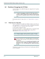
Page 46: ...16 The following adaptor is available RJ 48 to E1 75 dual BNC Part No AG2CA0001 No other hardware strapping is required To set an E1 T1 port to E1 75 connect an adaptor for E1 75 operations onto the...

Page 47: ...r time To install a blade 1 Wear an ESD Electrostatic Sensitive Devices wrist strap and attach it to one of the ground lugs on the SDM 9600 chassis Front ground lug located beneath the POWER ON LED Re...

Page 48: ...for that slot 4 Carefully remove the SDM 9606 blade from its protective packaging CAUTION Do not expose the blade to a magnetic field or electrostatic charge at any time Damage to its components could...

Page 49: ...Inc 4 11 Press the handle back toward the front face of the blade NOTE The right card handle is equipped with a microswitch that senses whether the blade is fully inserted It is very important that th...

Page 50: ...you wish to remove 2 Open both card handles slightly by pushing the lever in and opening the handle toward you The blue H S LED will blink indicating that the blade is NOT READY to be removed Caution...

Page 51: ...he blade the rest of the way out of the chassis Caution Do not expose the blade to a magnetic field or electrostatic charge at any time Damage to its components could result 6 Install a filler panel t...

Page 52: ...ler panel Part No 161 1140 000 to control the air flow Example An SDM 9600 installed with a single SDM 9606 blade requires 9 filler panels 4 in the empty front slots and 5 in the empty rear slots See...

Page 53: ...sible damage to the unit ensure that the 48 VDC power supply is shut OFF before you connect the SDM 9600 DC unit 2 Ensure that all blades and filler panels are fully inserted into their slots and secu...

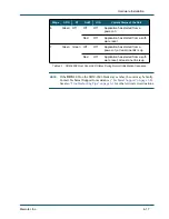
Page 54: ...M 9606 blades execute program decompression Signaling Engine software load and system test You can follow the system status from the console see next section or by watching the LEDs on the front of th...

Page 55: ...er critical error situations 6 Green Off Off Off Application has started from a power on Red Off Application has started from a soft ware reset 7 Green Green Off Off Application has started from a pow...

Page 56: ...erminal or PC or to a modem for dialup connection to a remote console 4 9 1 Important Console and Modem Settings for Startup The console port performs autobaud detection when in auto sensing mode The...

Page 57: ...es until the NetPerformer responds with a prompt for the user login 4 Enter the administrator login ADMIN This is the default login Additional user logins can be defined For details refer to the chapt...

Page 58: ...u should change the Emulation setting from Auto detect to ANSI as follows 1 Access HyperTerminal using the Windows Start button and drop down menus Start Programs Accessories Communications HyperTermi...

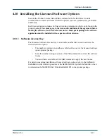
Page 59: ...ftware application must be installed with a separate software license 4 10 1 Software License Key The Memotec Software License Key is a traceable number that is used to activate the licensed software...

Page 60: ...bles are not provided with the SDM 9606 product package To connect the SDM 9606 blade to a LAN hub 1 Connect one end of the LAN cable to one of the Ethernet LAN ports on the blade labelled ETH 1 and E...

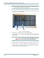
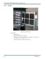
Page 61: ...lean the air filter 1 Unscrew the M2 5 screw located near the center of the fan unit front panel Refer to Figure 4 8 NOTE This screw can be loosened but not removed CAUTION Do not unscrew the knurled...

Page 62: ...rgent 5 Rinse thoroughly in water and allow to dry completely before replacing the filter in the fan unit WARNING To prevent electrical shock and damage to the unit do not install a wet air filter int...

Page 63: ...5 Memotec Inc 5 1 Product Description...

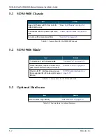
Page 64: ...filter Fan Unit on page 5 5 Table 5 1 Feature items for the SDM 9600 chassis Item Details 1 console port with console cable Console Port on page 5 13 2 Ethernet ports require customer sup plied LAN ca...

Page 65: ...SDM 9600 Chassis Equipped with SDM 9606 Blades 5 slots for blades 1 slot unavailable for blade POWER ON LED Ground Lug Fan Unit Rackmount Ears Card Handles Figure 5 2 Rear View of the SDM 9600 Chassi...

Page 66: ...gure 5 1 on page 3 POWER ON green goes on when the unit is powered on NOTE Other system status LEDs are located on the SDM 9606 blades OOS ST ALM and H S See page 8 5 4 3 Power Input Modules Dual powe...

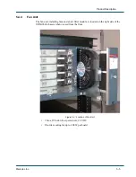
Page 67: ...t The fan unit including fans and an air filter module is located on the right side of the SDM 9600 chassis when viewed from the front 2 fans 290 cubic feet per minute 24 VDC Provides cooling for up t...

Page 68: ...Air Filter The air filter is Washable fabric Velcro type adherence to outer grill Maintenance or replacement possible after opening the 1 U fan tray refer to Cleaning the Air Filter on page 4 23 No to...

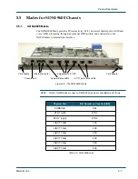
Page 69: ...r command line interface NOTE On the NetPerformer console SDM 9606 ports are identified as follows Figure 5 5 The SDM 9606 Blade Ethernet ports 2 Card handle System status LEDs E1 T1 port status LEDs...

Page 70: ...age 4 12 The E1 T1 port status LEDS are described on E1 T1 Port Status LEDs on page 5 16 State Interpretation Red Early stages of system startup when the bootstrap program is running Amber Later stage...

Page 71: ...col address source destination or SAP or custom filtering For information on connecting to the LAN hub refer to Connecting the LAN Hub on page 4 22 5 6 2 LAN Port Status LEDs Two LAN status indicators...

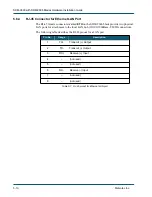
Page 72: ...9606 blade provide two physical LAN ports for attachment to the local LAN hub 10 100 1000Base T MDI connection The following table describes the RJ 45 pinout for a LAN port Pin No Usage Description 1...

Page 73: ...1 11 NOTE To determine whether any DSP modules are currently installed on the SDM 9606 blade power up the unit as described on Powering Up the Unit on page 4 15 The DSP type is displayed with the pro...

Page 74: ...SDM 9600 with SDM 9606 Blades Hardware Installation Guide 5 12 Memotec Inc products SDM 9360 SDM 9380 and SDM 9585...

Page 75: ...ing gender DTE DCE Protocol VT 100 or PPP Reverse console function also available for satellite applications SkyPerformer 5 8 2 Console Cable A console cable kit for the console port is included with...

Page 76: ...chment of the console cable It is a dedicated port with autosensing DTE DCE mode and autobaud The following table describes the RJ 45 pinout for the console port Pin No Usage Description 1 RTS Request...

Page 77: ...ps channelized digital connection at 100 Ohms with up to 24 timeslots E1 CEPT PCM 30 ISDN PRI Provides a 2 048 Mbps channelized digital connection with up to 32 timeslots software selectable at 75 or...

Page 78: ...ication SYN AL Off Either the port is not configured State DISABLED or it did not pass the power up self test and is not func tional Green The digital link is synchronized Amber One or more Yellow Ala...

Page 79: ...Cable RJ 48M to E1 75 dual BNC adaptor cable Ordering part number AG2CA0001 Installed between the digital port and the BNC coaxial cable Refer to page 8 Figure 5 7 RJ 48 to E1 75 Dual BNC Adaptor Cab...

Page 80: ...e European Union Steward ferrite 28A2024 0A0 Part No 332 0003 000 The following table describes the RJ 48 pinout required for E1 T1 ports NOTE An E1 T1 interface is hard strapped as NT by default for...

Page 81: ...6 Memotec Inc 6 1 Troubleshooting Tips...

Page 82: ...rst alarm has been logged with the notation M xx A xx D xx enter ER to dump the Exit Record Send to Technical Support Enter CE Clear ERR DIAG LED to turn the ALM LED off Unit starts with an alarm mess...

Page 83: ...mulator to 9600 bps and start again LAN connection does not work No power to LAN hub Make sure the DC power inlet has power Make sure the LAN hub is properly plugged in and switched on Incorrect cable...

Page 84: ...SDM 9600 with SDM 9606 Blades Hardware Installation Guide 6 4 Memotec Inc...

Page 85: ...7 Memotec Inc 7 1 Networking Features...

Page 86: ...r Optimization Voice FR EFR HR AMR 16K AMR 8K Data GPRS CS 1 to CS 4 EDGE MSC 1 to MSC 9 HSCSD Signaling 16K 32K 64K Concentrated and Non Concentrated Fax modem Short Message Service SMS Dual Rate Aut...

Page 87: ...over PowerCell or T 38 for SIP Super G3 configurable to passthrough or fallback to G3 Group IV fax and other non voice bearer ISDN channel at 64K over VoIP Fax signal types V 21 channel 2 V27ter 2400...

Page 88: ...hical star point to point satellite point to point multipoint with SkyPerformer option Automatic node discovery with least cost metric routing PPP dial backup time of day connect PowerCell node discov...

Page 89: ...ode Manager i NNMi software Menu driven asynchronous console port VT 100 via DB 9 male connector autosensing DTE DCE Remote Telnet access to command port FTP or Zmodem upload and download of software...

Page 90: ...SDM 9600 with SDM 9606 Blades Hardware Installation Guide 7 6 Memotec Inc...

Page 91: ...ing 4 18 startup setting 4 18 D Damage avoiding 4 6 4 10 4 13 D CH LED 5 16 Dimensions 5 4 Distance requirements 3 2 DSP module installation 4 4 DSPs 5 11 installation 4 5 location 4 4 E E1 T1 cable 5...

Page 92: ...ON LED 5 4 Power connecting to 4 15 Power up sequence 4 16 Product package 1 9 Product numbers 1 8 R Rack requirements 3 2 Requirements distance 3 2 environmental 3 2 location 3 2 materials 3 3 rack...

Page 93: ...SDM 9600 with SDM 9606 Blades Hardware Installation Guide Index 9...

Page 94: ...REACH FURTHER OFFER MORE Contact Memotec tel 1 514 738 4781 e mail MemotecSupport memotec com 7755 Henri Bourassa Blvd West Montreal Quebec Canada H4S 1P7 www memotec com...

Reviews: