background image

UE/BE 200-800, SE 200-400, ULE/SLE 400-800 
UP/BP/ULP/SLP 400-800 

13

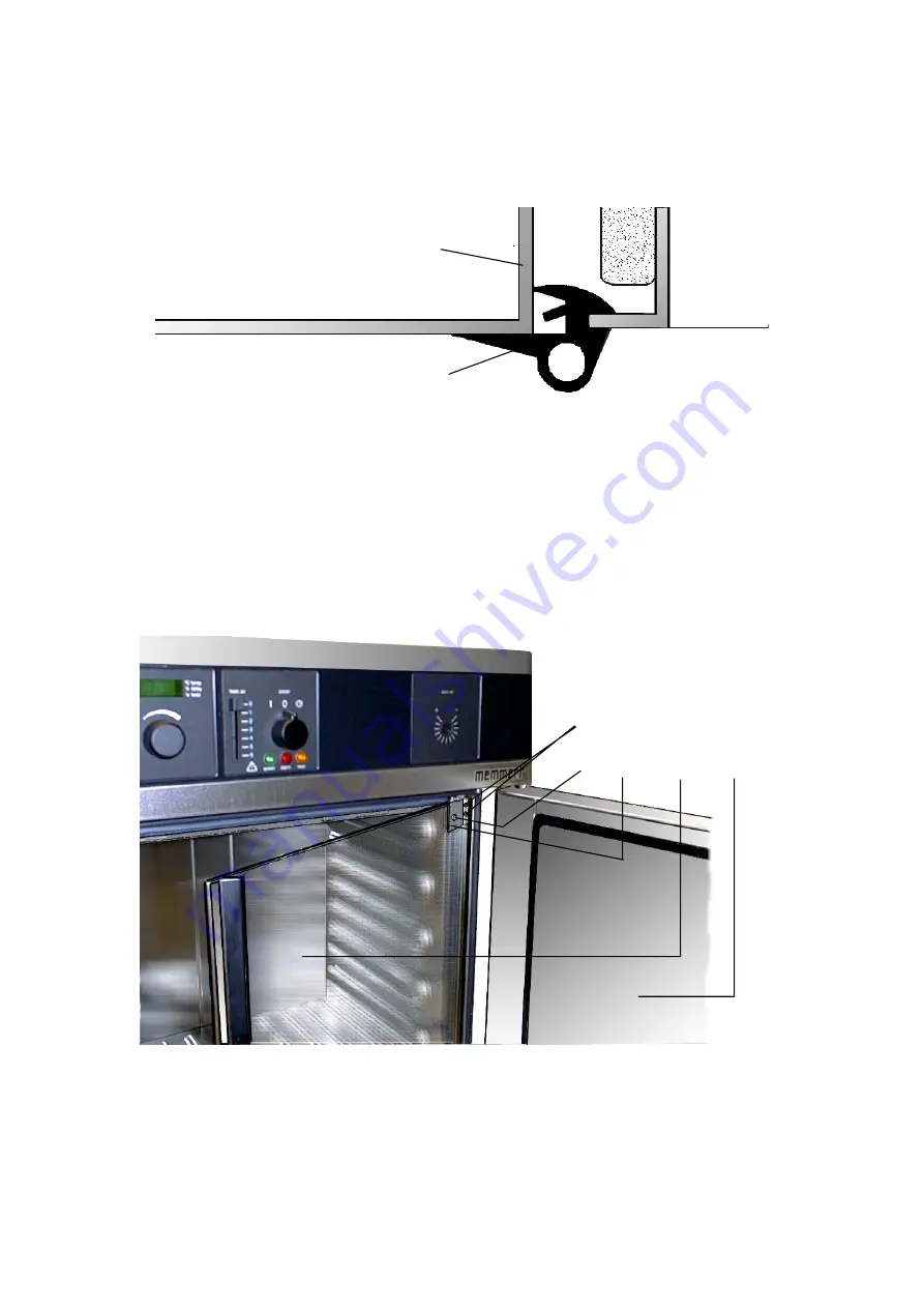
13  Changing the seal of the working chamber 


The seal of the working chamber can be pulled out after opening the door. The new 
one can be fitted in according to the illustration.  


The pre-cut seal should be inserted into the space without tension and then cut if 
required. 


14  Readjusting and dismantling the inner door on incubators BE / BP   


Loosen the screws (3) (do not unscrew them completely, otherwise the fixing block at 
the interior side will drop down). 


Adjust the door and tighten the screws (3) again. 


Check screw (4) and tighten it, if necessary. 


Adjust the inner door closure, if required. 


If a fixing block has dropped down, it will be accessible by pulling out the side parts 
(see chap. 15) and can be mounted in position again. 


For dismantling the glass door unscrew screw (4) (hold the nut at the opposite side with 
spanner SW 13), tilt the glass door forward and lift it out of the lower door hinge. 


Assemble in reverse order. 


1 Door 
2 Inner door 
3 Screws for adjustment 
4 Fixing screws (glass door) 
5 Hinge for inner door (top)


Housing Post 

Seal 

Working 
Chamber 


5  

2 1 

Summary of Contents for BE200

Page 1: ...SERVICEMANUAL UE BE 200 800 SE 200 400 ULE SLE 400 800 UP BP ULP SLP 400 800 08 98 ...

Page 2: ... module P Class 7 8 Removing the temperature limiter Class P 8 9 Changing the fuse for unit protection 8 10 Changing the fan motor 9 11 Changing the door lock door knob and or door seal 10 11 1 Changing the door lock door knob and or door seal on models 200 500 10 11 2 Changing the door lock door knob and or door seal on models 600 800 11 12 Dismantling the door 12 12 1 Readjusting the door 12 13 ...

Page 3: ... unit Separating the unit exposes raw metal edges therefore Always use gloves Before removing the top cover pull out the plug This Service manual describes the steps for the dismounting of the unit Reassembly is done in reverse order if not stated differently 1 Removing the top cover Pull out the plug Unscrew 4 screws at the back of the casing cover Slightly lift up the cover and remove it by pull...

Page 4: ... Disconnect all cables from main switch temperature controller and safety device unit Open the door On the right upper door hinge unscrew the left one of the two screws 1 approx 5 mm Slide the control panel to the left and remove it forwards with all control modules main switch temperature controller and safety device 1 ...

Page 5: ... ventilation flap Flat spring Adjusting spindle Slider Lock washer for bearing bracket 5 Changing the safety device module TWW TWB only E class Remove top cover see chap 1 Remove rear wall chap 15 Loosen fixing nut 5 of the temperature sensor clamp 4 inside the working chamber and take the sensor 3 out through the back of the working chamber and the intermediate plate ATTENTION Do not bend the cap...

Page 6: ...t through the ceiling and or the back panel of the working chamber Pull off the PT100 sensor from the 4 way terminal strip on the electronic controller Cut open the cable binder with side cutters and change the PT100 sensor The following panels can be dismantled in indicated manner Assemble in reverse order Warning Ensure that the PT100 sensor is fitted properly into the mounting clip Glass PT100 ...

Page 7: ...rking controller Cable connectors safety device Cable connectors additional power board Mounting blocks Fixing screws additional power board Temperature sensor Ribbon cable RS232 only on 3 phases units or 115 V Remove top cover see chap 1 Disconnect the cable connectors 5 from the working controller 1 if necessary mark them Disconnect RS 232 10 way ribbon cable 11 at the working controller Disconn...

Page 8: ...essary mark Disconnect ribbon cable 5 between working controller 1 and safety device 2 Disconnect RS 232 10 way ribbon cable 11 at the controller 1 upper multipole connector Disconnect ribbon cable parallel printer interface 12 at the controller Disconnect 10 way ribbon cable at the card reader lower multipole connector Disconnect PT100 connecting cable 10 4 way connector at the controller Disconn...

Page 9: ... the intermediate plate Disconnect all cable connectors 3 at the temperature limiter 1 Loosen screws 4 at the rear post of the casing cover and lift out temperature limiter 9 Changing the fuse for unit protection Remove top cover see chap 1 For changing the quick acting fuse 250V 15A push a flat screwdriver from the side under the fuse and lift it out of its clamp by twisting the screwdriver Push ...

Page 10: ... guide 5 is directed upwards Remove top cover see chap 1 Disconnect the earth connections on the rear wall and pull out the rear wall upwards Disconnect the earth cable and the connecting cables on the motor After releasing the hexagon nuts 1 the motor base plate with the fan motor has to be removed On the back of the fan motor base plate the screws 2 can now be unscrewed and the motor can be pull...

Page 11: ...11 1 2 Door knob The door knob can be dismantled in order of numbers 2 to 6 and assembled in reverse order 11 1 3 Door seal Unscrew the lock cover 10 Pull out the radiation shield 8 and remove the old seal Place the new silicone door seal 7 on the radiation shield 8 Fit in the radiation shield see sectional drawing A B and screw on the lock cover 1 Door 2 Disc for doorknob 3 Locking ring 4 Door kn...

Page 12: ...l On the left door remove radiation shield 10 with centre plate 17 and old seal Cut the ends of the new door seal according to the old one and place it on the radiation shield Fit in radiation shield see sectional drawing A B and screw it on On the left door fit in radiation shield and centre plate 1 Door 1 1 Door stiffener 2 Disc for door knob 3 Locking ring 4 Door knob 5 Guide screw 6 Sleeve 7 D...

Page 13: ...e setting notch of the eccentric points towards the front Insert the screws 2 again and tighten them Note It is essential that the long screw be inserted in the same position as illustrated See also chap 3 12 1 Readjusting the door After releasing the screw 12 ATTENTION Screw 12 is secured with glue Loosen it by a sharp tug with a 2 mm hexagon socket key the door can be adjusted by turning the ecc...

Page 14: ...ise the fixing block at the interior side will drop down Adjust the door and tighten the screws 3 again Check screw 4 and tighten it if necessary Adjust the inner door closure if required If a fixing block has dropped down it will be accessible by pulling out the side parts see chap 15 and can be mounted in position again For dismantling the glass door unscrew screw 4 hold the nut at the opposite ...

Page 15: ... the model Dismantle intermediate plate 6 Remove insulating mats 9 11 Remove circulation fan 14 according to Chap 10 model 800 has 2circulation fans mounted on the back wall of the working space Unscrew the screws for the air inlet 7 and lift out air inlet downwards Pull out seal for working chamber see chap 13 Dismantle the working chamber according to chap 17 16 Changing the heating After releas...

Page 16: ...ments are arranged properly Re assembly takes place in the reverse order of the numbers shown The air panel 1 has to be secured on the working chamber during re assembly using aluminium foil as follows Apply adhesive with a brush to foil and air panel and allow the adhesive to dry for about 1 minute Hold a spacing guide as indicated below against the back wall of the working chamber and secure the...

Page 17: ...r 4 Side panels 5 Rear wall 6 Intermediate plate 7 Air inlet 8 Air shaft 9 Insulating mat top 10 Insulating mats sides 11 Insulating mat back 12 Adjusting spindle for ventilation flap 13 Heating 14 Circulation fan only UL ovens 15 Working chamber 16 Air outlet 17 Heating sheets 3 5 4 6 9 10 17 11 7 10 15 13 2 1 ...

Page 18: ...mantled from the housing cage Pull out upwards both side panels 4 Unscrew screws 2 Remove the transit fitting 1 Release the tubing clips by pressing against the inner walls of the working chamber Take the working chamber backwards out of the housing cage When assembling check that the tubing clips are not bent top view x 1 2 4 Tubing clips Transit fitting Fibreglass seal Seal top view x ...

Page 19: ...ure E Class P Class E 0 Send controller back to Memmert for replacement E 1 E R R 1 Send controller back to Memmert for replacement E 2 E R R 2 Check the equipment fuses and if necessary replace them as described in Chap 9 Check the contactor in case of 3 phase ovens check also the electrical supply If the fault cannot be rectified remove the controller on 3 phase ovens including the additional po...

Page 20: ...f these instructions are disregarded We reserve the right to make changes in technical specifications Dimensions subject to confirmation 19 Our Address MEMMERT GmbH Co KG P O Box 17 20 91107 Schwabach Federal Republic of Germany 49 9122 925 0 Fax 49 9122 14585 Internet www memmert com Direct dialling the service department 49 9122 925 128 142 E Mail heinz bayer memmert com by MEMMERT GmbH Co KG fr...

Page 21: ...3776 B03777 clamp for fuse 3 phase E02611 800 B03779 B03780 Chap 11 1 4 side panel model right left 1 metal door model 200 B00408 200 B03786 B03785 300 B00420 300 B03786 B03785 400 B00432 400 B03788 B03787 500 B00444 500 B03790 B03789 2 6 door knob complete B00995 600 B03792 B03781 11 15 door lock with 2 6 B02600 700 B03794 B03793 11 16 door lock with 2 6 model 200 B02419 800 B03796 B03795 300 B02...

Page 22: ... ribbon cable 7 ribbon cable to parallel printer interface 7 ribbon cable to serial interface 7 front panel 4 fuse for unit protection 8 I incubators 13 inner door 13 14 insulating mat 14 L lock cover 10 lock washers 2 locking latches 6 M maintenance work 2 MEMory Card 18 modules safety device 4 7 modules working controller 6 7 mounting blocks 2 4 O our address 19 P pilot lamps 4 protective ground...

Page 23: ...UE BE 200 800 SE 200 400 ULE SLE 400 800 UP BP ULP SLP 400 800 22 ...

Page 24: ...D 08364 UE BE 200 800 SE 200 400 ULE SLE 400 800 UP BP ULP SLP 400 800 ...

Reviews: