

1. Before insertion of a contact into an insulator,
please review the insulator’s contact numbering
scheme so the ground and each contact is
placed into the proper hole.
2. Push the wired contact into the insulating block
until it stops and snaps into place.
3. Ensure its correct mounting by slightly pulling on
the contact.
4. The male contacts are solid for their entire
length and are inserted with the contact tip first
into the rear of the inlet/plug.
5. The female contacts consist of a flexible braid
and spring and are inserted with the contact tip
first into the rear of the lidded receptacle/connector.
6. Insert the Provided Hole Plugs into the unused
holes in the front of each insulating block.
Note: If a new Receptacle or Inlet is to mate with
a previously installed device, pay particular
attention to the number of contacts and
numbered position in the Receptacle or Inlet.
Continuity will not be obtained unless the male
and female contacts are evenly mated.
Disassembly of PN12c Contacts
1. To remove the contact from the insulating block,
the provided Multi-Contact Removal Tool 9-LD12-37
must be used. From the front side of the insulating
block, slide the contact removal tool over the contact.
2. Push until the contact pops out the back side of
the insulating block.
3.
Caution:
Each contact is designed to be
removed from the insulating block a maximum
of 3 times. New contacts should be used if
contacts are removed more than 3 times.
ASSEMBLY
Verify that power has been disconnected prior to assembly.
For In-Line Connections
Insert the cable through the handle and gasket. Strip
the cable jacket to provide a workable wire length,
being mindful that the jacket must extend into the
handle to achieve a secure grip. Then strip the wires
to the lengths indicated in table 4. When applicable
back out the terminal screws far enough (but not
completely) to allow the conductors to pass. Insert
the conductors fully into their respective terminals
and hand tighten to the torques indicated in table 5.
For Mounted Receptacles/Inlets
Insert the cable through the wall box and cut to allow
adequate length. Strip the cable jacket to allow a
workable wire length. Strip the individual cables to
the lengths indicated on Table 4. When applicable
back out the terminal screws far enough (but not
completely) to allow the conductors to pass. Insert
the conductors fully into their respective terminals
and hand tighten to the torques indicated in Table 5.
Assemble the receptacle/inlet and the color gasket
to the box with the appropriate hardware.
Hole Pattern for Custom Mounting
In applications where custom mounting to a panel or
box is desired, the clearance and mounting holes
should be drilled as indicated in the following diagram
and Table 7.
OPERATION
To ensure safe and reliable operation, Meltric plugs
and receptacles must be used in accordance with their
assigned ratings. They can only be used in conjunction
with mating receptacles or plugs manufactured by
Meltric or another licensed producer of products
bearing the
TM
technology trademark.
Meltric plugs & receptacles are designed with
different keying arrangements, so that only plugs and
receptacles with compatible contact configurations
and electrical ratings will mate with each other.
Connection
To connect, open the protective plug cap, align the
red dots on the plug and receptacle bodies, insert
plug into receptacle, apply force and rotate the plug
20° counterclockwise (CCW). The contacts will mate
and he circuit will close.
Disconnection
To open the circuit and remove the plug, press the
pawl, apply inward force and rotate the plug 20°
clockwise (CW). The plug can be safely withdrawn
from the receptacle. The plug contacts remain
shrouded until after the circuit is disconnected.
Close protective plug cap to prevent contamination
by dirt, dust or other debris.
LOCKOUT PROVISIONS
The plug cap can be locked with a locking pawl
except PNHT or PN12cSS.
Screw: Plug inserted or cap closed, turn the 5/16”
screw with an Allen key until it reaches the bottom.
Do not over tighten.
MAINTENANCE
Meltric products require little on-going maintenance.
However, it is a good practice to periodically perform
the following general inspections:
• Check the mounting screws for tightness.
• Verify that the weight of the cable is supported
by the strain relief mechanism and not by the
terminal connections.
• Check the IP gaskets for wear and resiliency.
In wet/wash-down environments, the gaskets
should be inspected periodically (6 months) for
wear and hardness. Replace gaskets as needed.
• Verify the electrical continuity of the ground
circuit every 6 months.
• Check the contact surfaces for cleanliness and pitting.
Deposits of dust or debris can be rubbed off the
contacts with a clean cloth. Under no circumstances
should the contact surfaces be filed since this will
remove the silver-nickel, butt-contact tip degrade
contact consistency. Sprays should not be used
since they tend to collect dirt. If any significant pitting
of the contacts or other serious damage is observed,
the device should be replaced.
Receptacle contacts may be inspected by qualified
personnel. This should only be done with the power
disconnected. Any repair or service must be
performed with genuine Meltric parts only.
MANUFACTURER’S RESPONSIBILITY
Meltric’s responsibility is strictly limited to the repair or
replacement of any product that does not conform to
the warranty specified in the purchase contract. Meltric
shall not be liable for any penalties or consequential
damages associated with the loss of production, work,
profit or any financial loss incurred by the customer.
Meltric Corporation shall not be held liable when its
products are used in conjunction with products not
bearing the
TM
technology trademark. The use
of Meltric products in conjunction with mating devices
that are not marked with the
TM
technology
trademark shall void all warranties on the product.
Meltric Corporation is a member of the international
association, BECMA: the Butt-contact Electrical
Connectors Manufacturers Association.
For more information, visit, www.becma.ch.
INSPN F
C
A
B
B
Table 7 - Custom Mounting Dimensions
‘A’
‘B’
‘C’
Model
Inches mm Inches mm Inches mm
PN20/30
2.00
50
1.65
42
.19
5.0
PN20HT/30HT 2.00
50
1.65
42
.19
5.0
PN7c
2.00
50
1.65
42
.19
5.0
PN12c
2.00
50
1.65
42
.19
5.0
PN12cSS
2.00
50
1.65
42
.19
5.0
Mount with the latch or
pawl at the top to
counteract the weight and
strain of the plug & cable.
Table 6 - Conductor Coding and Terminal Markings
Terminal ID
Function
“G”, “E” or GND
“N”
PN20/PN30/PN20HT/PN30HT Models
“1” or “R1” (Black)
“2” or “S2” (Red)
“3” or “T3” (Blue)
PN7c/PN12c Models
“1” to “6” or
“1” or “11”
“Hot” conductors, no specific lettered ter-
minal applies to any specific colored conductor
“Hot” conductors, no specific lettered ter-
minal applies to any specific colored conductor
White or gray, system ground
(neutral conductor only “N”)
Green equipment grounding conductor
only (or green with yellow stripe).
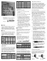
Compression
Nut
Handle
Strain
Relief
Color-Coded
Gasket
Receptacle (or Inlet)
Bushing


