

experience and knowledge if they are supervised or have been
instructed in how to use the unit safely and understand the associ-
ated hazards. Do not allow children to play with the unit. Cleaning
and user maintenance must not be carried out by children unless
they are supervised.
2.2 Intended use
The wireless humidity sensor must only be used to operate
M-WRG-II and M-WRG ventilation units. Any different or more
extensive usage will be regarded as contrary to the intended use.
The intended use also includes compliance with all the notes in
these instructions.
For any use contrary to the intended use, Meltem Wärmerückge-
winnung GmbH & Co. KG shall accept no liability for any damage
that may occur and offers no warranty that the components will work
perfectly and correctly.
3
Items supplied
— M-WRG-II FSF wireless humidity sensor
— 2x 1.5 V battery, size AA, Mignon
— 2x screws and dowels
4
Installation and set-up
NOTICE
Never install the wireless humidity sensor in a metal enclosure,
otherwise wireless communication between the wireless sensor
and ventilation unit will not be possible.
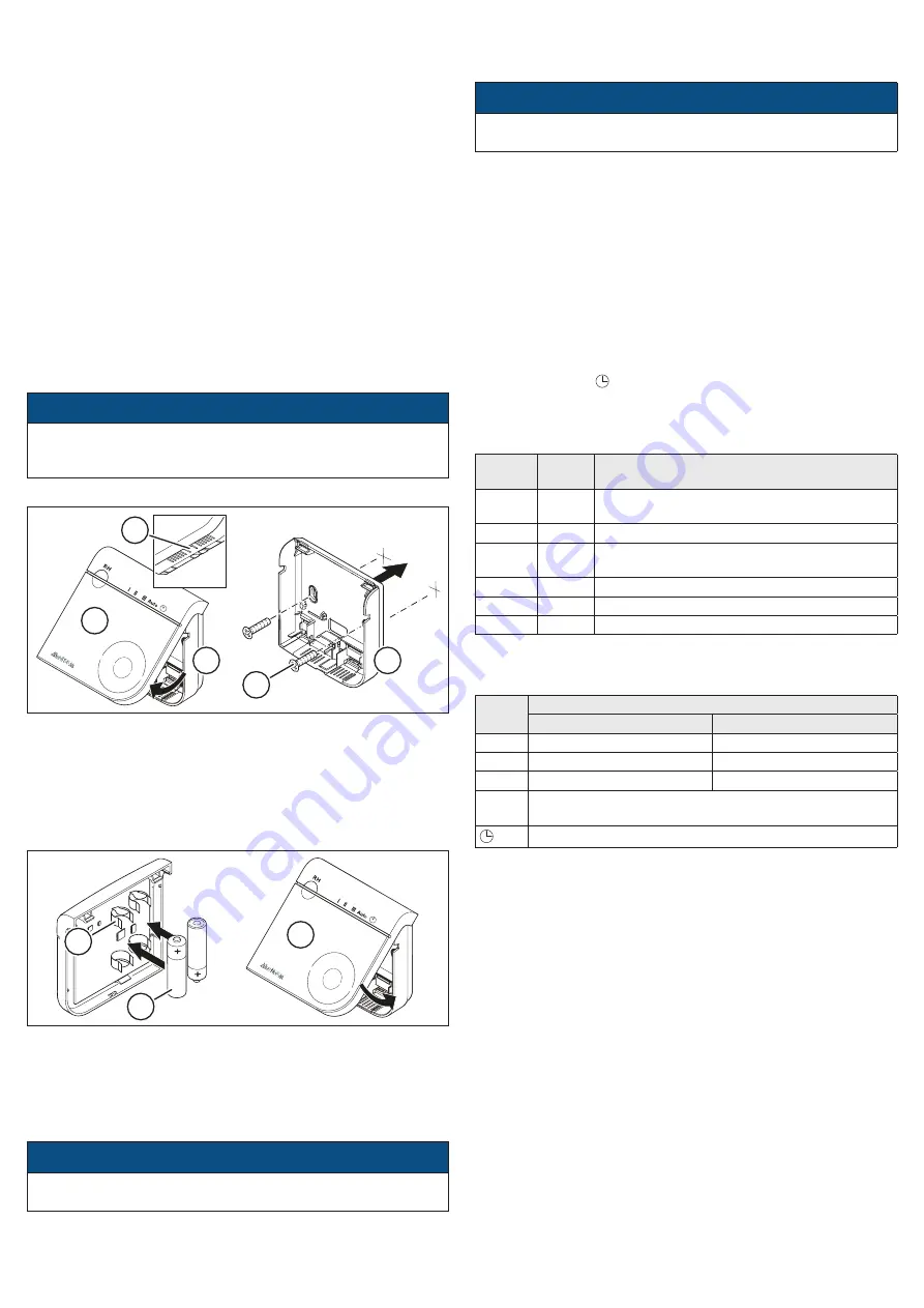
4.1 Fixing the housing to the wall
3
4
1
2
3
Fig. 2: Fixing the housing to the wall
►
Press the tab (item 1 in Fig. 2) on the underside of the housing
(item 3 in Fig. 2) and pull the cover (item 2 in Fig. 2) away from
the housing.
► Use the screws (item 4 in Fig. 2) and dowels provided to fix the
housing in the desired position.
4.2 Inserting the batteries and attaching the cover
1
2
3
Fig. 3: Inserting the batteries and attaching the cover
►
Insert the batteries (item 1 in Fig. 3) in the battery holders
(item 2 in Fig. 3) on the back of the cover.
All the LEDs light up for 3 seconds when the batteries are
inserted. The wireless sensor then switches automatically to
connection mode and the status LED flashes green-red.
NOTICE
Make sure that the battery polarity is correct. A sticker beside the
battery holders shows the correct battery orientation.
►
Insert the tabs on the cover into the cutouts in the housing.
►
Swivel the cover down until you hear it snap into place in the
4.3 Connecting to the ventilation unit for the first time
►
Switch the ventilation unit on. It remains in connection mode for
2 minutes.
NOTICE
When it is supplied, the wireless sensor is automatically set to
connection mode (status LED flashes green-red).
►
Tap the control button (item 1 in Fig. 1). The ventilation unit gives
an audible signal when the connection is established and the
status LED flashes green.
5
Operation
5.1 Checking the status / Selecting the ventilation
level/program
►
Tap the control button (item 1 in Fig. 1) to check the current
status. This is signalled by the status LED (item 2 in Fig. 1) and
the mode LEDs (item 3 in Fig. 1).
►
Tap the control button again while the status and mode LEDs
are lit to switch between the different ventilation levels/programs.
Your current selection is indicated by the mode LED beneath the
I
,
II
,
III
,
Auto
or symbol.
5.2 Status LED
The status LED (item 2 in Fig. 1) provides the following feedback
when the control button (item 1 in Fig. 1) is pressed:
LED
colour
LED
flashes
Description
Green
1x
The ventilation unit has received and is
carrying out the command
Red
1x
No wireless connection to the ventilation unit
Red
2x
The air filters in the ventilation unit need to be
changed
Red
3x
Error message from the ventilation unit
Red
4x
The wireless sensor is faulty
Red
5x
The batteries need to be changed
5.3 Mode LEDs
The green mode LEDs (item 3 in Fig. 1) indicate which ventilation
level or ventilation program is selected.
Mode
LED
Ventilation levels/programs (factory default settings)
M-WRG-II
M-WRG
I
Vent. level
I
: 10 / 20* m
3
/h
Vent. level
I
: 15 / 20* m
3
/h
II
Vent. level
II
: 30 / 40* m
3
/h
Vent. level
II
: 30 / 40* m
3
/h
III
Vent. level
III
: 50 / 60* m
3
/h
Vent. level
III
: 60 m
3
/h
Auto
Humidity control or
automatic mode (only for units with CO
2
sensor)
Intensive ventilation 100 m
3
/h for 15 min
* Options M-WRG-II O/LFS, M-WRG-II O/MVS or M-WRG O/LFS,
M-WRG O/MVS change the button assignment
5.4 Connecting to the ventilation unit again
►
Switch the ventilation unit on. It remains in connection mode for
2 minutes.
►
Tap the control button (item 1 in Fig. 1) several times until the
green
Auto
mode LED lights up.
►
Hold down the control button until the status LED (item 2 in
►
Release the control button. The wireless sensor switches to
connection mode and the status LED flashes green-red.
►
Tap the control button again. The ventilation unit gives an
audible signal when the connection is established and the status
LED flashes green.
6
Changing the batteries
►
The illustration in section 4 shows how to change the batteries.
7
Cleaning
Wipe the outer surfaces from time to time with a soft, damp cloth.
Use mild soapy water. Never use acidic, corrosive or abrasive
cleaning agents.


