background image

8

Installation

The radio remote clock has a built in AC power supply. After the power cable has been
connected, a green LED labeled Netz indicates that the clock is ready to operate. If the
antenna cable has been connected to both the antenna and the clock's BNC connector,
the brighness of the LED labeled Feldstärke reflects the signal strength of the 77.5
kHz carrier. In order to get the maximum signal, the antenna should be aligned in two
steps. First it should be turned slowly until the Feld LED is mostly dimmed. Finally
the antenna must be turned by 90° from this position to obtain maximum signal. The
antenna should be installed at least 30 cm away from the clock and from steel girders
or plates.

If the antenna is installed properly and the signal from DCF77 can be received

without strong distortions, the green LED labeled Modulation starts blinking exactly
once per second, corresponding to the time marks from DCF77. If this LED flashes
intermediately, there is some electrical noise around which prevents the microproces-
sor from decoding the time message. In this case, a better location for the antenna must
be found.

After reset, the red LED labeled Freilauf indicates that the clock is running on xtal

and has not synchronized with DCF77 yet. Due to the plausibility checks, it can take
up to three minutes after power-up until the clock is synchronized and this LED is
turned off. The state of this LED only changes when a new minute begins.

Frontview

Summary of Contents for DCF77C51

Page 1: ...DCF77C51 Technical Information Operating Instructions FUNKUHREN...

Page 2: ...Werner Meinberg Auf der Landwehr 22 D 31812 Bad Pyrmont Telefon 49 52 81 9309 0 Telefax 49 52 81 9309 30 Internet http www meinberg de E Mail info meinberg de May 28 2002...

Page 3: ...Port 9 Serial Input and Output Drivers 9 Transmission Speed 9 Framing 10 Output mode 10 Time Zone 10 Pulse Outputs 10 DIL Switches 11 Technical Specifications 12 CE Label 13 Format of the Meinberg St...

Page 4: ......

Page 5: ...some parity and status bits can be decoded from the time marks of the 15th up to the 58th second every minute The absence of any time mark at the 59th second of a minute signals that a new minute wil...

Page 6: ...6...

Page 7: ...current time message an additional plausibility check against the previous time message is performed If that plausibility check passes too the real time clock on the board is adjusted corresponding t...

Page 8: ...lled at least 30 cm away from the clock and from steel girders or plates If the antenna is installed properly and the signal from DCF77 can be received without strong distortions the green LED labeled...

Page 9: ...ivers need to be connected only if a serial string shall be sent on request Lever 10 of the DIL switch lets the user select either RS 232 input or current loop input It is not possible to use both the...

Page 10: ...new minute begins Levers 6 and 7 are used to select the desired mode of operation SW 6 SW 7 String Mode on on once persecond off on once perminute on off onrequestonly off off reserved Time Zone Lever...

Page 11: ...0 9600 19200 SW4 SW5 Framing 7E1 7E2 8N1 8N2 SW6 SW7 Output Mode per second per minute on request SW8 Timezone UTC MESZ MEZ SW9 reserved SW10 Serial Input 20mA RS232 default settings framing 7E2 baudr...

Page 12: ...rned off the on board RTC keeps the time based on XTAL for more than 48 hours gold cap rsp more than 10 years lithium battery RELIABILITY OF OPERATION Microprocessor supervisory circuit provides watch...

Page 13: ...coaxial RF connector BNC type POWER SUPPLY 230V AC 50Hz 15V only when using 20mA current loop PHYSICAL DIMENSIONS Rolec Technobox TBA 084 L x B x H 160mm x 81mm x 62mm AMBIENT TEMPERATURE 0 50 C HUMI...

Page 14: ...e day of the week 1 7 1 Monday hh mm ss the current time hh hours 00 23 mm minutes 00 59 ss seconds 00 59 or 60 while leap second uv clock status characters u clock has not synchronized after reset sp...

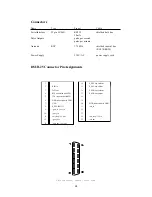
Page 15: ...ord DSUB 25 Connector Pin Assignments 1 14 P_SEC out collector 2 RxD in 15 P_SEC out emitter 3 TxD out 16 P_MIN out collector 4 RTS connected with CTS 17 P_MIN out emitter 5 CTS connected with RTS 18...

Page 16: ...16...

Page 17: ...17 Component Layout...

Page 18: ...shall be wired to operate as active output a connection from the pin labeled pass_out to Vcc 5V must be provided The pin labeled act_out is pulled down to the auxiliary 15V supply which must be made...

Page 19: ...he pin labeled pass_in to Vcc 5V must be provided The pin labeled act_in is pulled down to the auxiliary 15V supply which must be made available by the user active current loop input with auxiliary 15...

Page 20: ......

Reviews: