


K-200 Series • Updated 12-07
Page 2
9 7/8" [250mm]
1'-7 5/8"
[500mm]
8" [203mm] splash
guard [above table]
K-200: Table-to-table 6'-4 3/4" [1950mm]
K-200 PW: Table-to-table 8' 1/2" [2450mm] ‡
K-200 LPW: Table-to-table 9' 1/4" [2750mm] ‡‡
3 1/8"
[80mm]
1'-8
1/2"
[521mm]
3'-1"
[940mm]
2'-6
3/8"
[770mm]
4'-10"
[1474mm]
Door
open
6'-6
1/2"
[1994mm]
2'-10"
[864mm]
V
ertical
clearance
1'-6"
[458mm]
Horizontal
clearance
1'-8 1/8"
[510mm]
1'-1"
[330mm]
1'-1"
[330mm]
2'-2"
[660mm]
1
5/8"
[40mm]
2
3/4"
[70mm]
1'-0
1/4"
[310mm]
4
3/8"
[1
10mm]
3'-11 1/4" [1200mm]
1'-10
1/2"
[570mm]
6
7/8"
[174mm]
7
1/4"
[184mm]
table
support
lip
1'-1
1/4"
[335mm]
2'-10"
[864mm]
6'-4
1/8"
[1934mm]
6'-8
1/8"
[2034mm]
3
7/8"
[100mm]
2'-10"
[864mm]
4'-5
1/8"
[1350mm]
splash guard
[above table]
2'-6
1/4"
[770mm]
table
support
lip
drain
handle
control
panel
D
D
W
C
1 2 3
1'-4 1/8" [410mm]
9 5/8" [244mm]
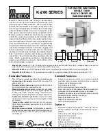
K-200, K-200 PW, K-200 LPW, electric heating
Machines without blower dryer, Left-to-Right
P
Prewash inserted here for
K-200 PW and K-200 LPW
K-200 PW: 1'-7 5/8" [500mm] prewash
K-200 LPW: 2'-7 1/2" [800mm] prewash
‡
‡‡
D
2'-1 5/8" [650mm]
2'-5 1/2" [750mm]
9-7/8" [250mm] load
section is replaced with
CSS Top section. Adds
1'-7 5/8" [500mm] to
overall machine length.
CSS TOP OPTION
(front view)
P
Prewash inserted here for
K-200 PW and K-200 LPW
9
1/4"
[235mm]
C
W
W
C
D
1 2 3
The vent shroud MUST NOT be connected directly to the machine, as this
prevents room air from being drawn into the shroud. All dimensions shown
are recommendations only. Actual exhaust connection must be adequate
for the exhaust air and comply with all applicable national and local codes.
The waste air connection must be corrosion-resistant and frost-free. In
particular, provision must be made to prevent air temperatures of 32°F/0°C
or colder from reaching the machine at any time. A provision for draining
moisture from the waste air pipe is STRONGLY RECOMMENDED.
UTILITY CONNECTIONS
Warm water connection (fill)
3/4" NPT female pipe connection
•
Temperature 110-140°F (43-60°C)
•
Pressure 15-25 PSI
•
Initial fill - Refer to Page 10
•
Hardness 4-6 grains/U.S. gal.
W
Electrical connection
3 (three) individual terminal blocks at locations
shown. Each connection is 4-wire with
ground (no neutral).
Incoming leads must be appropriately sized
for electrical supply. Opening(s) in the
machine for the supply lines are NOT
provided and should be executed on-site
using appropriate strain relief device(s).
Refer to Page 10 for supply details.
Individual disconnect
with lockout/tagout strongly recommended
for each supply (provided by customer).
Drain
2-15/16” (75mm) OD vertical, gravity-fed
drain outlet (HDPE piping). Optional 3" NPT
male adapter supplied. Recommend
placement directly above 4” floor drain.
Additional piping to drain (if so required) to
be supplied by customer.
D
Cold water connection (rinse)
3/4" NPT female pipe connection
•
Temperature 50°F (10°C)
•
Pressure 15-25 PSI
•
Consumption 84.7 U.S. gals./hour
•
Hardness 4-6 grains/U.S. gal.
C
Condensation
channel
Gap permits room
air to enter vent shroud
Condensation
can be drained
into machine
(drain is
supplied by
customer)
3
1/8"
[80mm]
Ø1'-1 3/8"
[340mm]
Ø1'-4"
[406mm]
Ø1'-6" [457mm]
3
7/8"
[100mm]
DETAIL VIEW: VENT
Vent shroud
(supplied
by customer)
Machine
exhaust vent
Vent connection
354 CFM (+120 CFM room air recommended)
1'-2
5/8"
[370mm]
1" [25mm]
1-3
3/4"
[20mm]


