


Page 15
S
ECTION
4 - O
PERATION
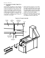
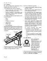
4.5 Clearing Jams
Under normal operating conditions, waste will
not jam inside the machine. However,
improper loading, or very large pieces of
waste, may cause a jam.
Most jams can be accessed simply by
opening the tank access door. A safety switch
shuts down the machine whenever the door
is opened during operation.
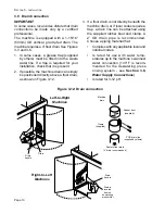
If the machine is equipped
with an external feeding
trough, wait until the
trough water drains into
the machine before
opening the door to
prevent splashout.
WARNING!
Never reach into the tank to clear a
jam. Instead, use a long wooden object
to clear a jam, such as a long wooden
spoon or the wooden handle of a
broom or mop.
To return the machine to operation, follow the
procedure in
Section 4.2,
Startup.
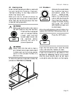
WARNING!
Before opening the access door, press
the OFF button to stop the machine.
Tank
access
door
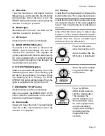
4.6 Shutdown
After all of the waste inside
the machine has been
processed, press the
STOP OPERATION
button. The machine will
enter a self-cleaning cycle
that should last approxi-
mately 15 minutes. During
this cycle, the STOP
OPERATION button will
be illuminated.
When the self-cleaning cycle is finished, the
lighted STOP OPERATION button will turn off.
Press the OFF button.
Open the front access door. Open the drain
valve, and allow the machine to drain.
Clean the machine as described in the
Section 5,
Cleaning
.
Meiko recommends
that the tank access door be left open
overnight to allow the tank to air thoroughly.