background image

18

Programming

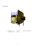
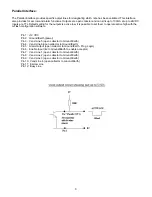
The Diagnostic Button on top of the GeoSL is capable of several functions:

  Enable a note in the currently installed dataset

  Disable a note in the currently installed dataset

 Field 

calibration

  Interface Switching (see page 7)

1)

Enable a note

Press the Diagnostic Button once, the Diagnostic LED will turn green and flash quickly.  Insert note to be
enabled, the GeoSL will pull the note inside then return it.  After note is returned, GeoSL will reboot.  Note
inserted is now enabled.

2)

Disable a note

Press the Diagnostic Button twice, the Diagnostic LED will turn red and flash quickly.  Insert note to be
disabled, the GeoSL will pull the note inside then return it.  After note is returned, GeoSL will reboot.  Note
inserted is now disabled.

3)

Field calibration

Press the Diagnostic Button 3 times, the Diagnostic LED will turn red and flash quickly.  Wait 2 seconds then
all front bezel LED’s will become lit.  Press Diagnostic Button to confirm.  Insert Calibration Paper when front
bezel LED’s flash quickly.  GeoSL will pull the calibration paper inside, cycle it several times then return it.
After calibration paper is returned, GeoSL will reboot.

4)

Interface Switching Mode

Press the Diagnostic Button 5 times to enter Interface Switching Mode.  Please see page 7 for details.

Note:  

Pressing the Diagnostic Button 4 times produces no effect.

Summary of Contents for Geo Gravity

Page 1: ...Operation Maintenance Manual MEI Inc 2008 254055001 Rev G3...

Page 2: ...L INTERFACE 8 ESCROW 9 ESCROW TIMING DIAGRAM 9 PARALLEL BINARY INTERFACE 10 CCTALK INTERFACE 11 TRUE RS232 12 TTL RS232 13 SERIAL INTERFACE 14 DIMENSIONAL DETAIL 15 GLASS MOUNT PLASTIC BEZEL ENTRY GUI...

Page 3: ...Mating Connector RS232 Jack Diagnostic Software Uploads Mounting Can be mounted at any angle Currency Range Notes 60mm through 85mm in width from center Acceptance Speed Approx 22 notes min Net Weight...

Page 4: ...4 Product detail 3 4 5 1 2 1 Bill Entry Area 3 Data Port 5 Upper section release button 2 Mounting Bracket BEG 4 I O Port...

Page 5: ...r the sensors located along the note path Thorough Cleaning To perform a more thorough cleaning of the Geo SL open the upper section by pressing on the two yellow release buttons and lift gently for f...

Page 6: ...front bezel LED s light up then release the button The GeoSL will reset and the new communication interface will be activated Note If the Interface Switching Mode is entered unintentionally do not pre...

Page 7: ...ollector to Ground Earth Pin 6 Enable Input tied to Ground Earth to enable acceptor Pin 12 Busy open collector to Ground Earth Active LOW when busy The Pulse Interface provides a corresponding signal...

Page 8: ...ate active high with the mFlash configuration software Pin 1 12 VDC Pin 2 Ground Earth power Pin 3 Vend Line 5 open collector to Ground Earth Pin 4 Vend Line 6 open collector to Ground Earth Pin 5 Ala...

Page 9: ...chine now has 25 seconds to accept or return this bill 3 If the host machine wishes to accept the bill then the escrow line should go high for at least 100mS stack command the bill acceptor will stack...

Page 10: ...ry credit information is sent as a low going output pulse 100mS which is sent simultaneously on the required lines This gives a maximum of 15 different denominations The output is determined by the in...

Page 11: ...ta pull up voltage 12V determined by external pull up voltage Supply sink Connector type 5 IDC 10 Slave device only CRC CCITT checksum Encryption Type 1 Minor release 0 Major release 4 IF Cable 252070...

Page 12: ...or special interface harness loom 9600 bps 1 start bit 1 stop bit 7 data bit format IF Cable VA WIRA09 Input Voltage 12 VDC Interface Module VA PCBA09 View facing left side of acceptor View facing tow...

Page 13: ...t 1 stop bit and 7 data bits IF Cable VA WIRA06 Input Voltage 12 VDC Pin1 12 VDC Pin 2 Ground Earth power Pin14 TTL RXD receive data to acceptor Pin 15 Common Pin 16 TTL TXD transmit data from accepto...

Page 14: ...1 12 VDC Pin 2 Ground Earth power Pin 5 Alarm Output open collector to Ground Earth Programmable Logic Pin 6 Enable Input tie to Ground Earth to enable acceptor Pin 7 Interrupt request to send data to...

Page 15: ...15 Dimensional Detail Glass mount plastic Bezel Entry Guide...

Page 16: ...16 Standard Mount Plastic Bezel Entry Guide...

Page 17: ...diagnostic LED found on the top of the Geo bill acceptor The codes are listed below System Reset Hold Reset Diagnostic Button Down for 5 Seconds SL S A XXX Series Model BEG Country ISO code Stackerle...

Page 18: ...rn red and flash quickly Insert note to be disabled the GeoSL will pull the note inside then return it After note is returned GeoSL will reboot Note inserted is now disabled 3 Field calibration Press...

Reviews: