


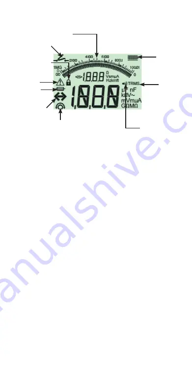
LCD Display
Figure 3 LCD display
In continuity mode, if a voltage greater than 25 V exists, testing
will be automatically inhibited and voltage measurement will be
displayed.
SP5 Switched probe
The SP5 switch probe allows the user to start a test by pressing the
[TEST] button on the probe, instead of on the instrument. This
allows for complete hands-free testing and increases user safety.
AC/DC voltage and frequency measurements
Note: Measured voltage must not exceed 600 V phase to earth or
Phase to Phase.
Note on TRMS measurement:
IN TRMS mode the instrument will measure both AC and DC
components of the supply voltage (AC+DC). In DC mode only the
DC component is measured.
1. Rotate selector switch to the ‘V’ position.
2. Connect test leads to the circuit under test.
3. Press the [TRMS] button to select DC or return to TRMS.
4. The measured voltage will be displayed on the main digital scale
in units of V or mV, as appropriate In TRMS mode, the measured
frequency (Hz) will be simultaneously displayed.
Insulation resistance testing - general
Safety note:
Insulation resistance testing is performed at high DC voltages and is
hazardous if touched. Always observe the safety precautions when
Auxiliary digital display
Continuity indicator
Lock indicator
Out of range
indicator
Lead null indicator
Audible alarm
indicator
Battery
condition
indicator
TRMS
indicator
Warning-refer to
user guide


