4
Speak or play music at the PC-end, you can use the built-in speaker of the device-end to listen.
Note
Please go to the Master Volume interface of the PC to set first if you want to use the dual-way
bidirectional talk. Please select Front Mic mode in the record control interface. (You can select
microphone enhanced in Advanced interface if the audio is too low.)
1.4
Alarm Setup
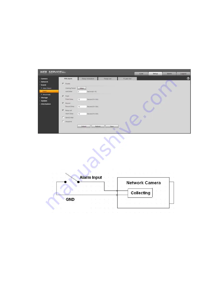
The alarm setup interface is shown as below. See Figure 1-3.
Figure 1-3
1.4.1 Alarm Input and Output Connection
Please refer to the following figure for alarm input information. See Figure 1-4.
Alarm input: When the input signal is idle or grounded, the device can collect the different statuses of
the alarm input port. When the input signal is connected to the 3.3V or is idle, the device collects the
logic “1”. When the input signal is grounded, the device collects the logic “0”.
Figure 1-4
Please refer to the following figure for alarm output information. See Figure 1-5.
Port NO and Port C composes an on-off button to provide the alarm output.
This button is normal open. The button becomes off when there is an alarm output.
Summary of Contents for MPIX-IP1MPIR30
Page 1: ...MPIX IP1MPIR30 Quick Start Guide Version 1 0 1 ...
Page 9: ...5 Figure 1 5 ...
Page 11: ...7 Figure 2 2 ...


