5695.B
09/04/08
16
N
1
®
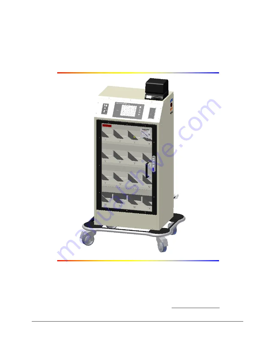
THE 1-LITER BAG WARMING SYSTEM
OPERATORS MANUAL
Medical Solutions, Inc.
3901 Centerview Drive, Suite L, Chantilly, VA 20151
(800) 435-7600 Phone • (703) 834-0039 Fax • www.warmiv.com
Page 1: ...5695 B 09 04 08 16N1 THE 1 LITER BAG WARMING SYSTEM OPERATORS MANUAL Medical Solutions Inc 3901 Centerview Drive Suite L Chantilly VA 20151 800 435 7600 Phone 703 834 0039 Fax www warmiv com...
Page 2: ...onditions 5 4 3 Electrical Requirements 5 5 0 Set up Instructions 6 5 1 The Documentor Resetting Instructions 7 5 1 1 Changing The Documentor Date 7 5 1 2 Changing The Documentor Time 8 5 2 Code Lock...
Page 3: ...ntenance Plan 13 7 1 Temperature Verification Procedures 13 Appendix A Electrical Schematics 14 Appendix B Fuse Installation 18 Appendix C Removing Service Panel 19 Appendix D Software License Agreeme...
Page 4: ...ture o Current time and date o Actual fluid temperature of each bag o Length of time each bag has been in the 16N1 The Documentor is designed to assist in the compliance with Joint Commission standard...
Page 5: ...t Point Temperature The Set Point identifies the desired temperature of the fluid bag This is preset by Medical Solutions Inc and can be changed by following the instructions found in Section 5 0 Set...
Page 6: ...he fluid bag has been recently placed in the heating compartment There is a seven 7 minute pre warming cycle after which the actual temperature and time in will be displayed 3 To open the 16N1 enter t...
Page 7: ...partment 16 Fluid bags should be placed with ports up and facing towards the door Thereafter bags should be removed from and replaced in the 16N1 in sequential order In the event you are unclear which...
Page 8: ...ating Temperature Room temperature to 104 F 10 C to 40 C Factory Preset Operating Temperature 104 F 40 C Certification MET Laboratory E112230 4 2 Ambient Operating Conditions Storage Temperature 22 F...
Page 9: ...gn the four 4 holes in the Time Clock Mounting Bracket and secure using the four 4 screws b Remove the three 3 screws in the back of The Documentor Attach The Documentor to the Mounting Bracket using...
Page 10: ...d Down buttons to adjust to the correct year e Press the Time Date button to move to the hour indicator Use the Up and Down buttons to adjust to the correct hour f Press the Time Date button to move t...
Page 11: ...r appears 17 Tap the right button The digits representing the month should flash 18 Tap the left button until the desired number appears 19 Tap the right button The digits representing the day should...
Page 12: ...lock must be in the open position with the button visible and the door to the 16N1 should be open 1 Press the red button located under the Code Lock handle see Figure 2 2 Enter the current Sub Master...
Page 13: ...d under the Code Lock handle 2 Enter the current User Code and verify a 1 second blue LED flash 3 Enter the new User Code and verify a 1 second blue LED flash 4 Enter the new User Code again and verif...
Page 14: ...f screen is powered on proceed to 2 2 Place a fluid bag into the compartment to be tested and wait 10 minutes 3 Does the fluid temperature and time appear on the Control Panel Display for the heating...
Page 15: ...be a discrepancy for the actual time heating for that fluid bag which will be reflected in the displayed Time In indicator The remaining heating compartments in the 16N1 can continue to be used Contac...
Page 16: ...mperatures 5 Select the fluid bag in heating compartment 1 6 With the outer wrap still on the fluid bag if applicable pierce the bag through the needle injection port on the bag with an 18ga needle to...
Page 17: ...L F use N 48 88 2 3 J1 J2 3 2 1 4 G N D 1 5 6 PL5 3 2 1 4 L N L N L L N N L L N N L N P1 P2 P3 P4 P 5 P 6 P 7 P 8 PL1 PL2 PL3 PL4 PL1 PL2 PL3 PL4 G N D Power Suppl y Cont rol B o ard DETAIL A Control...
Page 18: ...E AGREEMENT Drawing INITIALS INITIALS DRAWING STATUS Notes 1 B lack c olor Components 2 Red color Component Wiring I Matute 8 N 1 I Matute D Hendirx 5587A dwg 8N1 E lectrical Schematic 5587A Medical S...
Page 19: ...5695 B 16 Heater Plate Connector...
Page 20: ...5695 B 17 Heater Plate Connector...
Page 21: ...ore removing fuses To remove fuses place a slotted screwdriver into slot of fuse Turn counter clockwise and remove Replace fuses with same rating as fuse removed Insert fuse into fuse housing and turn...
Page 22: ...E M O V I N G S E R V I C E P A N E L Figure 7 Service Panel Remove the twelve 12 screws that attach the Service Panel Hold the handle and pull back and down until the Panel is free of the Unit Servic...
Page 23: ...MSI holds the copyright to the Software Use of the 16N1 implies acceptance of the terms of the Software License Agreement packaged with the unit ALL USERS SHOULD CAREFULLY READ THE TERMS AND CONDITION...
Page 24: ...In the event of a breach of this warranty during the Warranty Period MSI shall at its option repair or replace the Equipment Buyer s remedies are limited to such repair or replacement MSI DISCLAIMS AL...
Page 25: ...the provisions of the Operators Manual IMPORTANT THIS IS YOUR 16N1 WARRANTY REGISTRATION Please register your Warranty by filling out this page and sending it to Medical Solutions Inc within thirty 3...
Page 26: ...T In Service Sign In Sheet Date _______________________________________________________________________________________ Hospital _______________________________________________________________________...
Page 27: ...5695 B 24 Name Title Department Contact Number E mail Address...