


USB-2404-UI User's Guide
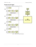
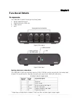
Functional Details
12
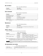
TEDS sensor connections
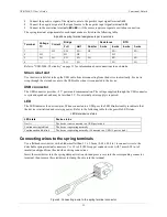
The USB-2404-UI supports class II TEDS "smart" sensors only. Connect the two TEDS lines to
TEDS Data
(T+) and
TEDS Common
(T–), and ensure that neither T+ nor T– is tied in common to any of the signal inputs
(terminals 3 through 6).
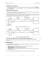
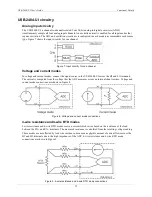
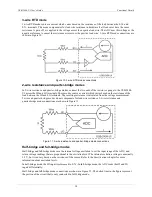
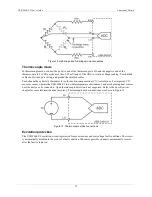
Signal source connections
You can connect ground-referenced or floating signal sources to the USB-2404-UI. For optimum signal quality,
use shielded cables and twisted pair wiring whenever possible.
When making a floating connection between the signal source and the USB-2404-UI, make sure the voltages on
the positive and negative connections are within the channel-to-earth voltage range. Refer to the
Specifications
chapter for operating voltages and information about overvoltage protection.
Figure 5. Connecting a grounded signal source
Figure 6. Connecting a floating signal source
Don't connect to signals or use for measurements within category III or IV
Refer to the "
Safety voltages"
section in the
Specifications
chapter for information about Measurement
Categories.
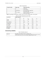
Timing options
The USB-2404-UI supports four timing options. Each option is optimized for different types of applications by
using different ADC conversion times.
High Speed
: optimized for high-speed applications at the expense of noise rejection.
Best 60 Hz Rejection
: optimized for rejection of 60 Hz noise.
Best 50 Hz Rejection
: optimized for rejection of 50 Hz noise.
High Resolution
: optimized for maximum overall noise rejection, and provides a good rejection of both
50 Hz and 60 Hz noise.
Refer to the analog input specifications for the conversion time and rejection ratio of each option.
Distributed by MicroDAQ.com, Ltd. www.MicroDAQ.com (603) 746-5524


